BTS7012-2EPA
PROFET™ +2 12V
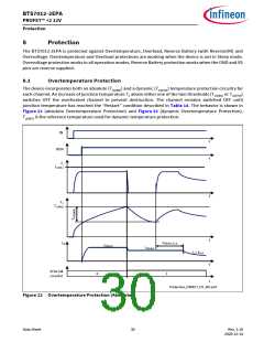
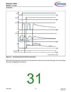
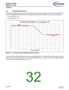
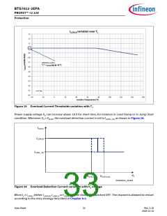
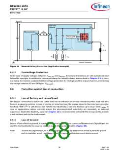
Protection
8.3
Protection and Diagnosis in case of Fault
Any event that triggers a protection mechanism (either Overtemperature or Overload) has 2 consequences:
•
•
The affected channel switches OFF and the internal counter is incremented
If the diagnosis is active for the affected channel, a current IIS(FAULT) is provided by IS pin (see Chapter 9.2.2
for further details)
The channel can be switched ON again if all the protection mechanisms fulfill the “restart” conditions
described in Table 14. Furthermore, the device has an internal retry counter (one for each channel) to
maximize the robustness in case of fault.
Table 14 Protection “Restart” Condition
Fault condition
Switch OFF event
“Restart” Condition
Overtemperature
TJ ≥ TJ(ABS) or (TJ - TJ(REF)) ≥ TJ(DYN)
TJ < TJ(ABS) and (TJ - TJ(REF)) < TJ(DYN)
(including hysteresis)
Overload
IL ≥ IL(OVL)
IL < 50 mA
TJ within TJ(ABS) and TJ(DYN) ranges
(including hysteresis)
8.3.1
Retry Strategy
When IN is set to “high”, the channel is switched ON. In case of fault condition the output stage is switched
OFF. The channel can be allowed to restart only if the “restart” conditions for the protection mechanisms are
fulfilled (see Table 14).
The channel is allowed to switch ON for nRETRY(CR) times before switching OFF. After a time tRETRY, if the input pin
is set to “high”, the channel switches ON again for nRETRY(NT) times before switching OFF again (“retry” cycle).
After nRETRY(CYC) consecutive “retry” cycles, the channel latches OFF. It is necessary to set the input pin to “low”
for a time longer than tDELAY(CR) to de-latch the channel (“counter reset delay” time) and to reset the internal
counter to the default value.
During the “counter reset delay” time, if the input is set to “high” the channel remains switched OFF and the
timer counting tDELAY(CR) is reset, starting to count again as soon as the input pin is set to “low” again. If the
input pin remains “low” for a time longer than tDELAY(CR) the internal retry counter is reset to the default value,
allowing nRETRY(CR) retries at the next channel activation.
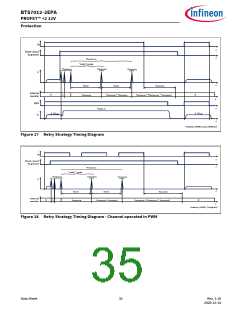
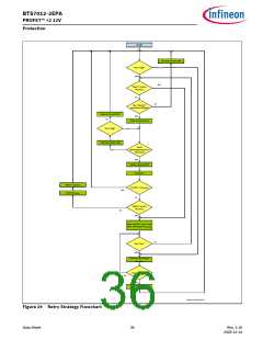
The retry strategy is shown in Figure 29 (flowchart), Figure 27 (timing diagram - input pin always “high”) and
Figure 28 (timing diagram - channel controlled in PWM).
Data Sheet
34
Rev. 1.10
2020-12-14

 INFINEON [ Infineon ]