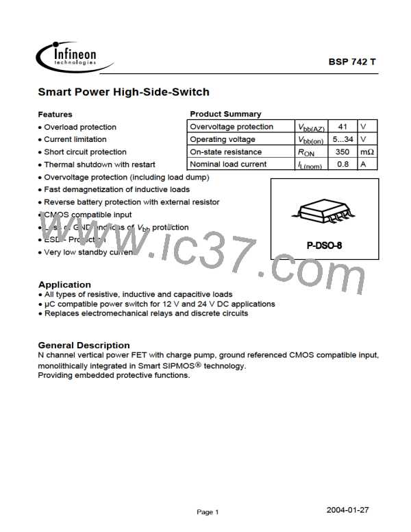
BSP 742 T
Block Diagram
+ V
bb
Voltage
source
Gate
protection
Overvoltage
protection
Current
limit
V Logic
OUT
Limit for
Charge pump
Level shifter
Rectifier
unclamped
ind. loads
Temperature
sensor
IN
Load
Logic
ESD
miniPROFET
GND
Load GND
Signal GND
Pin
1
2
3
4
Symbol
GND
IN
OUT
NC
Function
Logic ground
Input, activates the power switch in case of logic high signal
Output to the load
not connected
Vbb
Vbb
Vbb
Vbb
Positive power supply voltage
Positive power supply voltage
Positive power supply voltage
Positive power supply voltage
5
6
7
8
Pin configuration
Top view
•
Vbb
1
2
3
4
8
7
6
5
GND
IN
Vbb
Vbb
Vbb
OUT
NC
2004-01-27
Page 2

 INFINEON [ Infineon ]