SOT-89 Step up Switching Regulator with Shutdown
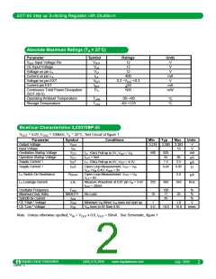
Absolute Maximum Ratings (TA = 25°C)
Parameter
Symbol
VOUT
VCE
Ratings
Units
V
V
V
mA
V
VOUT Input Voltage Pin
CE Input Voltage
Voltage on pin LX
Current on pin LX
Voltage on pin EXT
Current pin EXT
Continuous Total Power Dissipation
(SOT-89-5)
Operating Ambient Temperature
12
12
VLX
ILX
VEXT
IEXT
PD
12
400
0.3 ~VOUT +0.3
+50
mA
mW
500
οC
οC
TOPR
TSTG
-30~+80
Storage Temperature
-40~+125
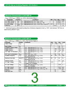
Elcetrical Characteristics ILC6370BP-50
VOUT = 5.0V, FOSC = 100kHz, TA = 25°C, Test Circuit of figure 1
Parameter
Output Voltage
Input Voltage
Symbol
VOUT
VIN
Conditions
Min
3.218
Typ
3.300
Max
3.383
10
Units
V
V
Oscillation Startup Voltage
Operation Startup Voltage
Supply Current 1
VST2
500
600
55
mA
µA
LX :10kΩ Pull-up to.5V, VOUT = VST
IOUT +1mA
VST1
86
2.5
IDD
1
2
1.5
LX :10kΩ Pull-up to.5V, VOUT = 4.5V
µA
Ω
Supply Current 1
IDD
Open Loop Measurement, VS/D = VIN,
VLX =VIN- 0.4V, VOUT = 3V
0.64
0.85
LX Switch-On Resistance
LX Leakage Current
RSWON
ILXL
Open Loop Measurement, VOUT = VIN,
VLX = 0V
Measure Waveform at EXT pin VIN = 3.6V
IOUT = 20mA
2.0
µA
255
10
300
345
KHz
Oscillator Frequency
Maximum Duty Ratio
Satndb-by Current
CE "High " Voltage
CE "Low " Voltage
FOSC
MAXDTY
ISTB
100
17
95
%
%
%
V
msec
No Load
25
VCEH
VCEL
Minimum VIN When Vref does not start up
Vref rises to 0V from 0.9V
1
6.0
1.8
16.0
10.0
Note: Unless otherwise spcified, VIN = VOUT x 0.6, IOUT = 50mA. See Schematic, figure 1.
Impala Linear Corporation
ILC6370/1 1.3
www.impalalinear.com
(408) 574-3939
July 1999
2

 IMPALA [ Impala Linear Corporation ]