ICS1893CF Data Sheet Rev. F - Release
Chapter 2 Conventions and Nomenclature
Chapter 2 Conventions and Nomenclature
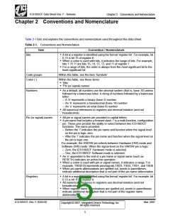
Table 2-1 lists and explains the conventions and nomenclature used throughout this data sheet.
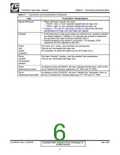
Table 2-1. Conventions and Nomenclature
Item
Convention / Nomenclature
Bits
• A bit in a register is identified using the format ‘register.bit’. For example, bit
0.15 is bit 15 of register 0.
• When a colon is used with bits, it indicates the range of bits. For example,
bits 1.15:11 are bits 15, 14, 13, 12, and 11 of register 1.
• For a range of bits, the order is always from the most-significant bit to the
least-significant bit.
Code groups
Colon (:)
Within this table, see the item ‘Symbols’
Within this table, see these items:
• ‘Bits’
• ‘Pin (or signal) names’
Numbers
• As a default, all numbers use the decimal system (that is, base 10) unless
followed by a lowercase letter. A string of numbers followed by a lowercase
letter:
– A ‘b’ represents a binary (base 2) number
– An ‘h’ represents a hexadecimal (base 16) number
– An ‘o’ represents an octal (base 8) number
• All numerical references to registers use decimal notation (and not
hexadecimal).
Pin (or signal) names
• All pin or signal names are provided in capital letters.
• A pin name that includes a forward slash ‘/’ is a multi-function, configuration
pin. These pins provide the ability to select between two ICS1893CF
functions. The name provided:
– Before the ‘/’ indicates the pin name and function when the signal level
on the pin is logic zero.
– After the ‘/’ indicates the pin name and function when the signal level on
the pin is logic one.
For example, the HW/SW pin selects between Hardware (HW) mode and
Software (SW) mode. When the signal level on the HW/SW pin is logic:
– Zero, the ICS1893CF Hardware mode is selected.
– One, the ICS1893CF Software mode is selected.
• An ‘n’ appended to the end of a pin name or signal name (such as
RESETn) indicates an active-low operation.
• When a colon is used with pin or signal names, it indicates a range. For
example, TXD[3:0] represents pins/signals TXD3, TXD2, TXD1, and TXD0.
• When pin name abbreviations are spelled out, words in parentheses
indicate additional description that is not part of the pin name abbreviation.
Registers
• A bit in a register is identified using the format ‘register.bit’. For example, bit
0.15 is bit 15 of register 0.
• All numerical references to registers use decimal notation (and not
hexadecimal).
• When register name abbreviations are spelled out, words in parentheses
indicate additional description that is not part of the register name
abbreviation.
ICS1893CF, Rev. F, 03/01/07
Mar. 2007
Copyright © 2007, Integrated Device Technology, Inc.
All rights reserved.
5

 ICSI [ INTEGRATED CIRCUIT SOLUTION INC ]