ICS1531 Data Sheet - Preliminary
Chapter 10 Timing Diagrams
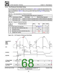
10.3.2 Two-Pixels-per-Clock Mode Timing
For 2-pixels-per-clock mode, Reg 30:6 must be cleared to ‘0’. Table 10-4 lists pixel characteristics for this
mode, as determined by Reg 2:0. (Both ‘A’ and ‘B’ channel pixels are pipelined and aligned with the rising
edge of the ADCRCLK.) Table 10-5 lists time measures for this mode, and Figure 10-6 shows timing
characteristics.
Table 10-4. Pixel Characteristics for 2-Pixels-per-Clock Mode
Reg 2:0
Setting
Pixel Characteristics When Reg 30:6 is Cleared to ‘0’
Total Number of Pixels
Total number is even.
Total number is odd.
Pixel Output
What the Pixels Represent
0
1
Output is on Channel ‘A’. Samples taken on half-rate ADCRCLK’s rising edge.
Output is on Channel ‘B’. Samples taken on half-rate ADCRCLK’s falling edge.
Table 10-5. Timing for 2-Pixels-per-Clock Mode
Time
Timing Description
Min
Typ
Max Units
Period
Tp, Td CLK Period, CLK Duty Cycle
–
–
See Table 10-3.
–
–
ns
ns
ns
ns
ns
t1
t2
t3
t4
CLK Rise Time to ADCRCLK Rise Time
2.6
t2 = 2 × Tp
TBD
ACDRCLK Period
–
–
ACDRCLK Fall Time to ADCSYNC Rise Time
Digital Data Transition
–
–
3.8
5
TBD
Figure 10-6. AC Timing for 2-Pixels-per-Clock Mode
P+1
P+4
Analog Data In:
P
P+3
ARED
AGRN
ABLUE
P+5
P+2
Tp, Td
CLK
t1
t2
ADCRCLK
ADCSYNC
t3
t4
‘A’ Channel Digital
Data Output
P-6
P-5
P-4
P-3
P-2
P-1
P
‘B’ Channel Digital
Data Output
P+1
ICS1531 Rev N 12/1/99
December, 1999
Copyright © 1999, Integrated Circuit Systems, Inc.
All rights reserved.
68

 ICSI [ INTEGRATED CIRCUIT SOLUTION INC ]