ICS1531 Data Sheet - Preliminary
Chapter 10 Timing Diagrams
Chapter 10 Timing Diagrams
10.1 Industry-Standard 2-Wire Serial Bus Timing Diagrams
10.1.1 Start and Stop Conditions
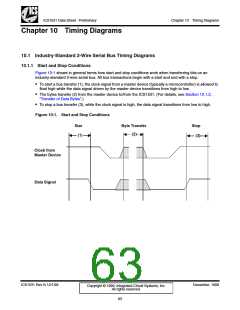
Figure 10-1 shows in general terms how start and stop conditions work when transferring bits on an
industry-standard 2-wire serial bus. All bus transactions begin with a start and end with a stop.
• To start a bus transfer (1), the clock signal from a master device (typically a microcontroller) is allowed to
float high while the data signal driven by the master device transitions from high to low.
• The bytes transfer (2) from the master device to/from the ICS1531. (For details, see Section 10.1.2,
“Transfer of Data Bytes”.)
• To stop a bus transfer (3), while the clock signal is high, the data signal transitions from low to high.
Figure 10-1. Start and Stop Conditions
Star
(1)
Byte Transfer
(2)
Stop
(3)
Clock from
Master Device
Data Signal
ICS1531 Rev N 12/1/99
December, 1999
Copyright © 1999, Integrated Circuit Systems, Inc.
All rights reserved.
63

 ICSI [ INTEGRATED CIRCUIT SOLUTION INC ]