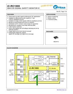
iC-RC1000
SIN/COS SIGNAL SAFETY MONITOR IC
Rev B1, Page 5/10
ABSOLUTE MAXIMUM RATINGS
These ratings do not imply permissible operating conditions; functional operation is not guaranteed.
Exceeding these ratings may damage the device.
Item Symbol
No.
Parameter
Conditions
Unit
Min.
-0.3
-10
Max.
G001 V(VCC)
G002 I(VCC)
G003 Vin()
G004 Iin()
Voltage at VCC1, VCC2
7
25
7
V
Current in VCC1, VCC2
mA
V
Voltage at PSIN, NSIN, PCOS, NCOS
Current in PSIN, NSIN, PCOS, NCOS
Voltage at ERR, OK
-0.3
-10
10
7
mA
V
G005 Vout()
G006 Iout()
G007 Ilu()
-0.3
-10
Current in ERR, OK
25
100
mA
mA
Pulse Current in all pins
(latch-up susceptibility)
according to Jedec Standard No. 78;
Ta = 25 °C, pulse duration to 10 ms,
-100
VCC1 = VCC1max, VCC2 = VCC2max
Vlu() = (-0.5...+1.5) x Vpin()max
,
G008 Vd()
ESD Susceptibility at all pins
HBM 100pF discharged through 1.5 kΩ
2
kV
THERMAL DATA
Operating conditions: VCC1 = 5 V ±10 %, VCC2 = 5 V ±10 %
Item Symbol
No.
Parameter
Conditions
Unit
°C
Min. Typ. Max.
-40 110
T01 Ta
Operating Ambient Temperature Range
(extended range on request)
T02 Rthja
Thermal Resistance Chip to Ambient
30
K/W
All voltages are referenced to ground unless otherwise stated.
All currents flowing into the device pins are positive; all currents flowing out of the device pins are negative.

 ICHAUS [ IC-HAUS GMBH ]