iC-HD7
QUAD DIFFERENTIAL LINE DRIVER
Rev A5, Page 6/8
APPLICATION NOTE
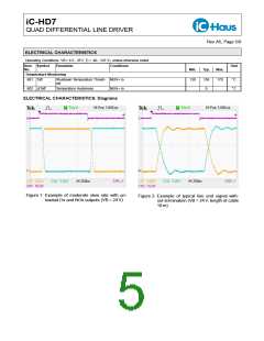
Reverse polarity and circuit protection
Since the reverse polarity protection diode D prevents
For reverse polarity protection electronic circuitry are discharging of the load capacitor C, especially at low
usually powered via a diode D in the supply line. Un- power consumption injected charge through distur-
der normal operating conditions, this diode will not af- bances may in general result in capacitor voltage ex-
fect function of the circuitry when the additional forward ceeding maximum ratings, leading to malfunction or
voltage drop across the diode is accounted for operat- destruction of circuitry and associated parts. Thus
ing voltage specification.
EMC requirements will afford more external circuitry
due to the introduction of a reverse polarity diode.
If the supply voltage Vsupply is suddenly reversed, a
load capacitor C may be still fully charged. Therefore,
the diode D has to be selected to withstand a voltage Figure 3 shows the iC-HD7 with the diode D for reverse
difference of at least twice the maximum supply volt- polarity protection and additional protective devices TS
age.
and ZD.
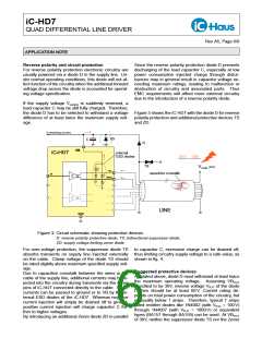
Figure 3: Circuit schematic showing protective devices
D: reverse polarity protective diode; TS: bidirectional suppressor diode;
ZD: supply voltage limiting zener diode
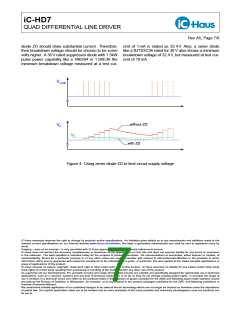
For over-voltage protection, the suppressor diode TS to capacitor C, excessive charge can be drained off,
absorbs transients on supply line injected externally thus limiting circuitry supply voltage to a safe value, as
on the cable. Clamp voltage of the diode TS should shown in fig. 4.
be rated slightly above maximum specified supply volt-
age.
Suggested protective devices
Due to capacitive crosstalk between the wires in the
As stated above, diode D must withstand at least twice
cable of the supply line, additional currents may be in-
the maximum operating voltage. Assuming VBmax
jected into the circuitry during transients via the driver
specified to be 30V, reverse voltage VR,D of the diode
pins of iC-HD7 connected directly to the cable. These
D then should be at least 60 V. Current rating de-
currents can be passed to ground or to VB by the in-
pends on total power consumption of the circuitry, but
ternal ESD diodes of the iC-HD7. Whereas negative
is usually below 1 amps. Therefore, typical 1 amps
current injection will simply be drained off to ground,
rated rectifier diodes like 1N4002 (with VR,D = 100 V)
positive current injection will charge capacitor C fur-
through 1N4007 (with VR,D = 1000 V) or equivalent
ther to higher voltages.
types (BA157 through BA159) can be used. At VBmax
By introducing an additional Zener diode ZD in parallel
of 30V, neither the suppressor diode TS nor the Zener

 ICHAUS [ IC-HAUS GMBH ]