3A L.D.O. VOLTAGE REGULATOR (Adjustable & Fixed)
LM1085
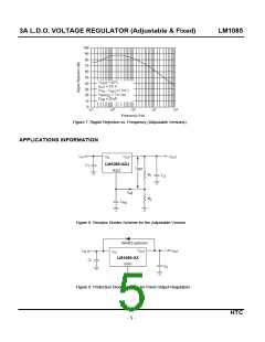
RIPPLE REJECTION
The ripple rejection values are measured with the adjustment pin bypassed. The impedance of the adjust pin
capacitor at the ripple frequency should be less than the value of R1 (normally 100Ω to 120Ω) for a proper
bypassing and ripple rejection approaching the values shown. The size of the required adjust pin capacitor is
a function of the input ripple frequency. If R1=100Ω at 120Hz the adjust pin capacitor should be 25uF.
At 100kHz only 0.22uF is needed.
The ripple rejection will be a function of output voltage, in circuits without an adjust pin bypass capacitor.
The output ripple will increase directly as a ratio of the output voltage to the reference voltage (VOUT/VREF
)
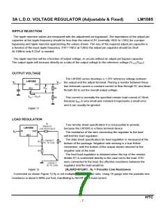
OUTPUT VOLTAGE
The LM1085 series develops a 1.25V reference voltage between
the output and the adjust terminal. Placing a resistor between these
two terminals causes a constant current to flow through R1 and down
throuth R2 to set the overall output voltage.
LM1085
This current is normally the specified minium load current of 10mA.
Because IADJ is very small and constant it represents a small error
and it can usually be ignored.
Figure 11.
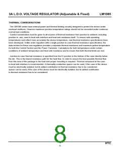
LOAD REGULATION
True remote sheet specification it is not possible to provide,
because the LM1085 is a three terminal device.
LM1085
The resistance of the wire connecting the regulator to the load
will limit the load regulation.
The data sheet specification for load regulation is measured at the
bottom of the package. Negative side sensing is a true Kelvin
connection, with the bottom of the output divider returned to the
negative side of the load.
The best load regulation is obtained when the top of the resistor
divider R1 is connected directly to the case not to the load. If R1
were connected to the load, the effective resistance between the
regulator and the load would be:
Figure 12.
[RPX(R2+R1)]/R1 , RP = Parasitic Line Resistance
Connected as shown Figure.12 R is not multiplied by the divider ratio. Using 16-gauge wire the parasitic line
P
resistance is about 0.004Ω per foot, transllating to 4mV/ft at 1A load current.
HTC
- 7 -

 HTC [ HTC KOREA TAEJIN TECHNOLOGY CO. ]