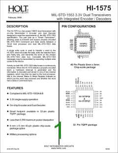
HI-1575
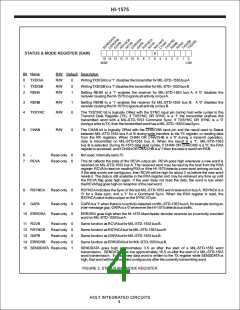
STATUS & MODE REGISTER (SAM)
0
15 14 13 12 11 10
MSB
9
8
7
6
5
4
3
2
1
0
LSB
Bit Name
R/W Default Description
0
1
2
TXDISA
R/W
R/W
R/W
0
0
1
WritingTXDISAto a '1' disables the transmitter for MIL-STD-1553 busA
WritingTXDISB to a '1' disables the transmitter for MIL-STD-1553 bus B
TXDISB
RENA
Setting RENA to a '1' enables the receiver for MIL-STD-1553 bus A. A '0' disables the
receiver causing the HI-1575 to ignore all activity on busA.
3
4
RENB
R/W
R/W
1
0
Setting RENB to a '1' enables the receiver for MIL-STD-1553 bus B. A '0' disables the
receiver causing the HI-1575 to ignore all activity on bus B.
TXSYNC
The TXSYNC bit is logically ORed with the SYNC input pin during host write cycles to the
Transmit Data Register (TX). If TXSYNC OR SYNC is a '1' the transmitter prefixes the
transmitted word with a MIL-STD-1553 Command Sync. If TXSYNC OR SYNC is a '0'
during a write toTX, then the transmitted word has a MIL-STD-1553 Data Sync.
5
CHAN
R/W
0
The CHAN bit is logically ORed with the CHA/CHB input pin and the result used to Select
between MIL-STD-1553 bus A or B during write transfers to the TX register, or reading data
from the RX registers. When CHAN OR CHA/CHB is a '0' during a transmit operation,
data is transmitted on MIL-STD-1553 bus A. When the result is a '1', MIL-STD-1553
bus B is selected. During HI-1575 data read cycles, if CHAN OR CHA/CHB is a '0', the RXA
register is accessed, and if CHAN OR CHA/CHB is a '1' then the data is read from RXB.
6
7
-
Read-only
Read-only
0
0
Not used. Internally set to '0'.
RCVA
This bit reflects the state of the RCVA output pin. RCVA goes high whenever a new word is
received on MIL-STD-1553 bus A. The received word may be read by the host from the RXA
register. RCVA is reset on reading RXA or if the HI-1575 detects a new word arriving on bus A.
If the data words are contiguous, then RCVA will be high for about 3 us before the new word
resets it. The data is still available in the RXA register and may be retreived any time up until
the RCVA flag goes high again. If the user does not read the data, the word is lost when
the RCVAflag goes high on reception of the next word.
8
9
RSYNCA
GAPA
Read-only
0
RSYNCA indicates the Sync of the last MIL-STD-1553 word received on bus A. RSYNCA is a
'0' for a Data sync, and a '1' for a Command Sync. When the RXA register is read, the
RSYNCAvalue is also output on the SYNC I/O pin.
Read-only
Read-only
0
0
GAPAis a '1' when there is no activity detected on MIL-STD-1553 busA, for example during an
inter-message gap. GAPAis a '0' whenever the HI-1575 detects bus traffic.
10 ERRORA
ERRORA goes high when the HI-1575 Manchester decoder receives an incorrectly encoded
word on MIL-STD-1553 busA
11 RCVB
Read-only
Read-only
Read-only
Read-only
0
0
0
0
1
Same function as RCVAbut for MIL-STD-1553 bus B.
Same function as RSYNCAbut for MIL-STD-1553 bus B.
Same function as GAPAbut for MIL-STD-1553 bus B.
Same function as ERRORAbut for MIL-STD-1553 bus B.
12 RSYNCB
13 GAPB
14 ERRORB
15 SENDDATA Read-only
SENDDATA goes high approximately 3.5 us after the start of a MIL-STD-1553 word
transmission. SENDATA goes low approximately 18.5 us after the start of a MIL-STD-1553
word transmission. If new a new data word is written to the TX register while SENDDATA is
high, that word will be transmitted contiguously after the currently transmitting word.
FIGURE 2. STATUS AND MODE REGISTER
HOLT INTEGRATED CIRCUITS
4

 HOLTIC [ HOLT INTEGRATED CIRCUITS ]