HT46R64/HT46C64
Functional Description
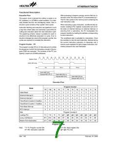
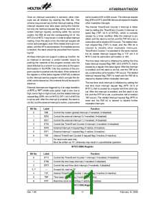
Execution Flow
After accessing a program memory word to fetch an in-
struction code, the value of the PC is incremented by 1.
The PC then points to the memory word containing the
next instruction code.
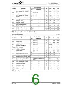
The system clock is derived from either a crystal or an
RC oscillator or a 32768Hz crystal oscillator. It is inter-
nally divided into four non-overlapping clocks. One in-
struction cycle consists of four system clock cycles.
When executing a jump instruction, conditional skip ex-
ecution, loading a PCL register, a subroutine call, an ini-
tial reset, an internal interrupt, an external interrupt, or
returning from a subroutine, the PC manipulates the
program transfer by loading the address corresponding
to each instruction.
Instruction fetching and execution are pipelined in such
a way that a fetch takes one instruction cycle while de-
coding and execution takes the next instruction cycle.
The pipelining scheme makes it possible for each in-
struction to be effectively executed in a cycle. If an in-
struction changes the value of the program counter, two
cycles are required to complete the instruction.
The conditional skip is activated by instructions. Once
the condition is met, the next instruction, fetched during
the current instruction execution, is discarded and a
dummy cycle replaces it to get a proper instruction; oth-
erwise proceed to the next instruction.
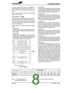
Program Counter - PC
The program counter (PC) is 12 bits wide and it controls
the sequence in which the instructions stored in the pro-
gram ROM are executed. The contents of the PC can
specify a maximum of 4096 addresses.
T
1
T
2
T
3
T
4
T
1
T
2
T
3
T
4
T
1
T
2
T
3
T
4
S
y
s
t
e
m
C
l
o
c
k
O
S
C
2
(
R
C
o
n
l
y
)
P
C
P
C
+
1
P
C
+
2
P
C
F
e
t
c
h
I
N
S
T
(
P
C
)
E
x
e
c
u
t
e
I
N
S
T
(
P
C
-
1
)
F
e
t
c
h
I
N
S
T
(
P
C
+
1
)
E
x
e
c
u
t
e
I
N
S
T
(
P
C
)
F
e
t
c
h
I
N
S
T
(
P
C
+
2
)
E
x
e
c
u
t
e
I
N
S
T
(
P
C
+
1
)
Execution Flow
Program Counter
Mode
*11 *10
*9
0
0
0
0
0
0
0
*8
0
0
0
0
0
0
0
*7
0
0
0
0
0
0
0
*6
0
0
0
0
0
0
0
*5
0
0
0
0
0
0
0
*4
0
0
0
0
1
1
1
*3
0
0
1
1
0
0
1
*2
0
1
0
1
0
1
0
*1
0
0
0
0
0
0
0
*0
0
0
0
0
0
0
0
Initial Reset
0
0
0
0
0
0
0
0
0
0
0
0
0
0
External Interrupt 0
External Interrupt 1
Timer/Event Counter 0 Overflow
Timer/Event Counter 1 Overflow
Time Base Interrupt
RTC Interrupt
Skip
Program Counter+2
@7 @6 @5 @4 @3 @2 @1 @0
Loading PCL
*11 *10
#11 #10
*9
*8
#8
S8
Jump, Call Branch
Return From Subroutine
#9
#7
S7
#6
S6
#5
S5
#4
S4
#3
S3
#2
S2
#1
S1
#0
S0
S11 S10 S9
Program Counter
Note: *11~*0: Program counter bits
#11~#0: Instruction code bits
S11~S0: Stack register bits
@7~@0: PCL bits
Rev. 1.80
7
February 14, 2006
图片预览")
 HOLTEK [ HOLTEK SEMICONDUCTOR INC ]