HT37B90/HT37B70/HT37B50/HT37B30
No matter what the source of the wake-up event is, once
a wake-up situation occurs, a time period equal to 1024
system clock periods will be required before normal sys-
tem operation resumes. However, if the wake-up has
originated due to an interrupt, the actual interrupt sub-
routine execution will be delayed by an additional one or
more cycles. If the wake-up results in the execution of
the next instruction following the ²HALT² instruction, this
will be executed immediately after the 1024 system
clock period delay has ended.
source instead of the internal WDT oscillator. If the in-
struction clock is used as the clock source, it must be
noted that when the system enters the Power Down
Mode, as the system clock is stopped, then the WDT
clock source will also be stopped. Therefore the WDT
will lose its protecting purposes. In such cases the sys-
tem cannot be restarted by the WDT and can only be re-
started using external signals. For systems that operate
in noisy environments, using the internal WDT oscillator
is therefore the recommended choice.
Under normal program operation, a WDT time-out will
initialise a device reset and set the status bit TO. How-
ever, if the system is in the Power Down Mode, when a
WDT time-out occurs, only the Program Counter and
Stack Pointer will be reset. Three methods can be
adopted to clear the contents of the WDT and the WDT
prescaler. The first is an external hardware reset, which
means a low level on the RES pin, the second is using
the watchdog software instructions and the third is via a
²HALT² instruction.
Watchdog Timer
The Watchdog Timer is provided to prevent program
malfunctions or sequences from jumping to unknown lo-
cations, due to certain uncontrollable external events
such as electrical noise. It operates by providing a de-
vice reset when the WDT counter overflows. The WDT
clock is supplied by one of two sources selected by con-
figuration option: its own self contained dedicated inter-
nal WDT oscillator or fOSC/8. Note that if the WDT
configuration option has been disabled, then any in-
struction relating to its operation will result in no opera-
tion.
There are two methods of using software instructions to
clear the Watchdog Timer, one of which must be chosen
by configuration option. The first option is to use the sin-
gle ²CLR WDT² instruction while the second is to use
the two commands ²CLR WDT1² and ²CLR WDT2². For
the first option, a simple execution of ²CLR WDT² will
clear the WDT while for the second option, both ²CLR
WDT1² and ²CLR WDT2² must both be executed to
successfully clear the WDT. Note that for this second
option, if ²CLR WDT1² is used to clear the WDT, succes-
sive executions of this instruction will have no effect,
only the execution of a ²CLR WDT2² instruction will
clear the WDT. Similarly, after the ²CLR WDT2² instruc-
tion has been executed, only a successive ²CLR WDT1²
instruction can clear the Watchdog Timer.
The internal WDT oscillator has an approximate period
of 65ms at a supply voltage of 5V. If selected, it is first di-
vided by 256 via an 8-stage counter to give a nominal
period of 17ms. Note that this period can vary with VDD,
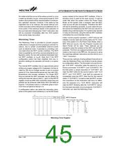
temperature and process variations. For longer WDT
time-out periods the WDT prescaler can be utilized. By
writing the required value to bits 0, 1 and 2 of the WDTS
register, known as WS0, WS1 and WS2, longer time-out
periods can be achieved. With WS0, WS1 and WS2 all
equal to 1, the division ratio is 1:128 which gives a maxi-
mum time-out period of about 2.1s.
A configuration option can select the instruction clock,
which is the system clock divided by 8, as the WDTclock
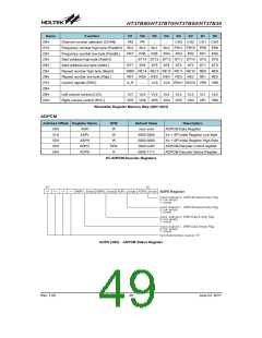
Watchdog Timer Register
Rev. 1.00
45
June 22, 2017

 HOLTEK [ HOLTEK SEMICONDUCTOR INC ]