HT37B90/HT37B70/HT37B50/HT37B30
Configuration
Option
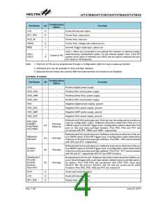
Pad Name
I/O
Function
AUD_IN
VBIAS
RES
I
O
I
Power Amp. input pin
¾
¾
¾
Power Amp. voltage bias reference pin.
Schmitt Trigger reset input, active low
OSC1, OSC2 are connected to an external RC network or external crystal,
determined by configuration option, for the internal system clock. If the RC
system clock option is selected, pin OSC2 can be used to measure the sys-
tem clock at 1/8 frequency.
OSC1
OSC2
I
Crystal or RC
O
Note: 1. Each pin on PA can be programmed through a configuration option to have a wake-up function.
2. Individual pins can be selected to have pull-high resistors.
3. Because the two timers are used by MIDI the external timer pin functions are disabled.
Absolute Maximum Ratings
Supply Voltage ..........................VSS-0.3V to VSS+5.5V
Input Voltage .............................VSS-0.3V to VDD+0.3V
IOL Total ..............................................................150mA
Total Power Dissipation .....................................500mW
Storage Temperature ...........................-50°C to 125°C
Operating Temperature ..........................-40°C to 85°C
IOH Total............................................................-100mA
Note: These are stress ratings only. Stresses exceeding the range specified under ²Absolute Maximum Ratings² may
cause substantial damage to the device. Functional operation of this device at other conditions beyond those listed
in the specification is not implied and prolonged exposure to extreme conditions may affect device reliability.
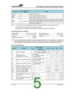
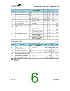
D.C. Characteristics
Ta=25°C
Test Conditions
Symbol
Parameter
Min.
Typ.
Max.
Unit
VDD
Conditions
fOSC=12.8MHz (37B50/30)
fOSC=12.8MHz (37B90/70)
2.4
3.0
¾
3.0
¾
8
5.5
5.5
12
V
V
VDD
Operating Voltage
¾
No load,
3V
5V
mA
Operating Current
IDD
fOSC=8MHz~12.8MHz,
DAC disable
(Crystal OSC or RC OSC)
20
30
mA
¾
3V
5V
3V
5V
¾
1
2
¾
¾
¾
¾
¾
¾
¾
¾
¾
¾
12
25
-4
-8
mA
mA
mA
mA
V
No load, system HALT,
WDT disable
ISTB1
Standby Current (WDT Disable)
Standby Current (WDT Enable)
5
¾
No load, system HALT,
WDT enable
ISTB2
10
¾
VIL1
VIH1
VIL2
VIH2
0.3VDD
VDD
0.4VDD
VDD
Input Low Voltage for I/O Ports
Input High Voltage for I/O Ports
Input Low Voltage (RES)
0
¾
¾
¾
¾
0.7VDD
0
V
¾
V
¾
0.9VDD
6
Input High Voltage (RES)
V
¾
3V
5V
3V
5V
mA
mA
mA
mA
¾
¾
¾
¾
I/O Port Segment Logic Output
Sink Current
IOL
VOL=0.1VDD
VOH=0.9VDD
10
-2
I/O Port Segment Logic Output
Source Current
IOH
-5
Rev. 1.00
5
June 22, 2017

 HOLTEK [ HOLTEK SEMICONDUCTOR INC ]