HT46R4A
System Architecture
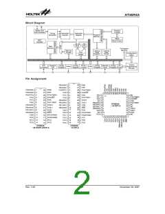
A key factor in the high-performance features of the
Holtek microcontrollers is attributed to the internal sys-
tem architecture. The range of devices take advantage
of the usual features found within RISC microcontrollers
providing increased speed of operation and enhanced
performance. The pipelining scheme is implemented in
such a way that instruction fetching and instruction exe-
cution are overlapped, hence instructions are effectively
executed in one cycle, with the exception of branch or
call instructions. An 8-bit wide ALU is used in practically
all operations of the instruction set. It carries out arith-
metic operations, logic operations, rotation, increment,
decrement, branch decisions, etc. The internal data
path is simplified by moving data through the Accumula-
tor and the ALU. Certain internal registers are imple-
mented in the Data Memory and can be directly or
indirectly addressed. The simple addressing methods of
these registers along with additional architectural fea-
tures ensure that a minimum of external components is
required to provide a functional I/O and A/D control sys-
tem with maximum reliability and flexibility.
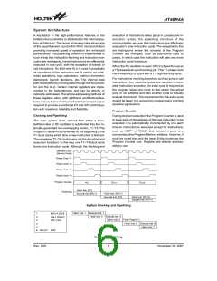
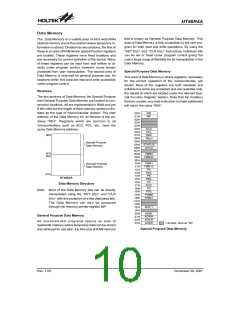
execution of instructions takes place in consecutive in-
struction cycles, the pipelining structure of the
microcontroller ensures that instructions are effectively
executed in one instruction cycle. The exception to this
are instructions where the contents of the Program
Counter are changed, such as subroutine calls or
jumps, in which case the instruction will take one more
instruction cycle to execute.
When the RC oscillator is used, OSC2 is freed for use as
a T1 phase clock synchronizing pin. This T1 phase clock
has a frequency of fSYS/4 with a 1:3 high/low duty cycle.
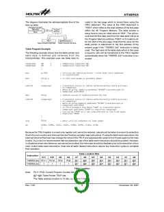
For instructions involving branches, such as jump or call
instructions, two machine cycles are required to com-
plete instruction execution. An extra cycle is required as
the program takes one cycle to first obtain the actual
jump or call address and then another cycle to actually
execute the branch. The requirement for this extra cycle
should be taken into account by programmers in timing
sensitive applications
Program Counter
Clocking and Pipelining
During program execution, the Program Counter is used
to keep track of the address of the next instruction to be
executed. It is automatically incremented by one each
time an instruction is executed except for instructions,
such as ²JMP² or ²CALL² that demand a jump to a
non-consecutive Program Memory address. However, it
must be noted that only the lower 8 bits, known as the
Program Counter Low Register, are directly address-
able by user.
The main system clock, derived from either a Crys-
tal/Resonator or RC oscillator is subdivided into four in-
ternally generated non-overlapping clocks, T1~T4. The
Program Counter is incremented at the beginning of the
T1 clock during which time a new instruction is fetched.
The remaining T2~T4 clocks carry out the decoding and
execution functions. In this way, one T1~T4 clock cycle
forms one instruction cycle. Although the fetching and
O
s
c
i
l
l
a
t
o
r
C
l
o
c
k
(
S
y
s
t
e
m
C
l
o
c
k
)
P
h
a
s
e
C
l
o
c
k
T
1
P
h
a
s
e
C
l
o
c
k
T
2
P
h
a
s
e
C
l
o
c
k
T
3
P
h
a
s
e
C
l
o
c
k
T
4
P
r
o
g
r
a
m
C
o
u
n
t
e
r
P
C
P
C
+
1
P
C
+
2
F
e
t
c
h
I
n
s
t
.
(
P
C
)
P
i
p
e
l
i
n
i
n
g
E
x
e
c
u
t
e
I
n
s
t
.
(
P
C
-
1
)
F
e
t
c
h
I
n
s
t
.
(
P
C
+
1
)
E
x
e
c
u
t
e
I
n
s
t
.
(
P
C
)
F
e
t
c
h
I
n
s
t
.
(
P
C
+
2
)
E
x
e
c
u
t
e
I
n
s
t
.
(
P
C
+
1
)
System Clocking and Pipelining
F
e
t
c
h
I
n
s
t
.
1
E
x
e
c
t
u
t
e
I
n
s
t
.
2
1
1
2
3
4
5
6
M
C
O
V
A
,
[
E
1
2
H
]
F
e
c
h
I
n
s
t
.
E
x
e
c
u
t
e
I
n
s
t
.
2
A
P
L
L
L
D
L
A
Y
F
e
t
c
h
I
n
s
t
.
3
F
l
u
s
h
P
i
p
e
l
i
n
e
C
[
1
2
H
]
F
e
t
c
h
I
n
s
t
.
6
E
x
e
c
t
u
t
e
I
n
s
t
.
7
6
:
F
e
c
h
I
n
s
t
.
:
D
E
L
A
Y
:
N
O
P
Instruction Fetching
Rev. 1.00
6
November 28, 2007

 HOLTEK [ HOLTEK SEMICONDUCTOR INC ]