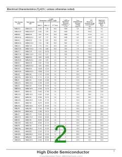
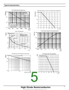
Typical Characteristics
FIG1:Peak Pulse Power Rating Curve
FIG2: Pulse Power or Current vs. Initial Junction Temperature
100
100
10
不重复脉冲波形见图 3
Non-Repetitive Pulse
Waveform shown in Fige.3
TA=25℃
75
50
1.0
25
0
0.31×0.31"(8.0×8.0mm)
Copper Pad Areas
0.1
0
25
50
75
100
125
150
175 200
0.1μs
1μs
10μs
100μs
1.0ms
10ms
TJ(℃)
td(μs)
FIG4:Typical Transient Thermal Impedance
FIG3: Pulse Waveform
100
150
tr=10μs
TJ=25℃
Pulse Width(td) is defined as
the Point where the Peak
Current Decays to 50% of IPPM
Peak Value
IPPM
10
100
50
0
Half Value - IPP
2
IPPM
1
10/1000μs Waveform as
Defined by R.E.A.
td
0.1
0
1.0
2.0
3.0
4.0
0.001
0.01
0.1
1
10
100
1000
tp(s)
t(ms)
FIG5: Maximum Non-Repetitive Surge Current
FIG6:Steady State Power Dissipation
7
6
5
4
3
2
1
200
TJ=TJMax.
8.3ms Single Half Sine-Wave
100
50
10
0
10
100
Number of Cycles
00
25
50
75
100 125 150 175 200
TL(℃)
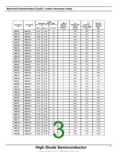
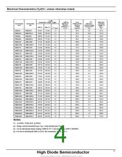
5
H
igh Diode Semiconductor

 HDSEMI [ Jiangsu High diode Semiconductor Co., Ltd ]