HIP5600
transfer. The latter because the TO-220 package permits
easy heat sinking.
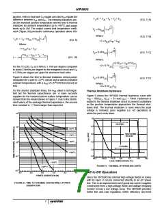
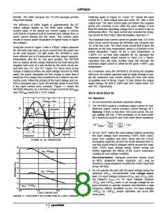
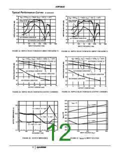
Referring again to Figure 10, Curve “A1” shows the input
current for a 10mA output load and curve “B1” with a 3mA
output load. The input current spike just before the negative
going zero crossing occurs while the input voltage is less
than the minimum operating voltage but is so short it has no
detrimental effect. The input current also includes the charg-
ing current for the 0.02µF input decoupling capacitor C1.
The efficiency of either supply is approximately the DC
output voltage divided by the RMS input voltage. The
resistor value, in the typical low current supply, is chosen
such that for maximum load at minimum line voltage there is
some current flowing into the zener. This resistor value
results in excess power dissipation for lighter loads or higher
line voltages.
The maximum load current cannot be greater than 1/2 of the
short circuit current because the HIP5600 only conducts over
1/2 of the line cycle. The short circuit current limit (Figure 38)
depends on the case temperature, which is a function of the
power dissipation. Figure 38 for a case temperature of
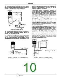
Using the circuit in Figure 3 with a 1000µF output capacitor
the HIP5600 only takes as much current from the power line
as the load requires. For light loads, the HIP5600 is even
more efficient due to it’s interaction with the output capacitor.
Immediately after the AC line goes positive, the HIP5600
tries to replace all the charge drained by the load during the
negative half cycle at a rate limited by the short circuit cur-
rent limit (see “A1” and “B1” Figure 10). Since most of this
charge is replaced before the input voltage reaches its RMS
value, the power dissipation for this charge is lower than it
would be if the charge were transferred at a uniform rate dur-
ing the cycle. When the product of the input voltage and cur-
rent is averaged over a cycle, the average power is less than
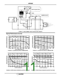
if the input current were constant. Figure 11 shows the
o
+100 C (i.e. no heat sink) indicates for AC operation the
maximum available output current is 10mA (1/2 x 20mA).
Operation from full wave rectified input will increase the
o
maximum output current to 20mA for the same +100 C case
temperature.
As a reminder, since the HIP5600 is off during the negative
half cycle, the output capacitor must be large enough to sup-
ply the maximum load current during this time with some
acceptable level of droop. Figure 10 also shows the output
ripple voltage, for both a 10mA and 3mA output loads “A2”
and “B2”, respectively.
HIP5600 efficiency as a function of load current for 80V
and 132VRMS inputs for a 15.6V output.
RMS
Do’s And Don’ts
DC Operation
120V
RMS
, 60Hz
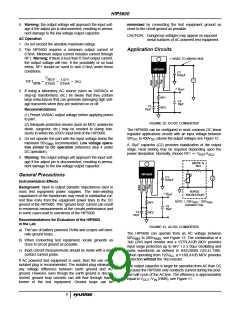
1. Do not exceed the absolute maximum ratings.
2. The HIP5600 requires a minimum output current of 1mA.
Minimum output current includes current through RF1.
Warning: If there is less than 1mA load current, the out-
put voltage will rise. If the possibility of no load exists,
RF1 should be sized to sink 1mA under these conditions.
I
IN
20mA/DIV.
A1
B1
V
B2
REF
1.07V
1mA
RF1
= ------------------ = --------------- = 1kΩ
MIN
1mA
V
OUT
A2
100mV/DIV.
3. Do not “HOT” switch the input voltage without protecting
the input voltage from exceeding ±650V. Note: induc-
tance from supplies and wires along with the 0.02µF
decoupling capacitor can form an under damped tank cir-
cuit that could result in voltages which exceed the maxi-
mum ±650V input voltage rating. Switch arcing can
further aggravate the effects of the source inductance
creating an over voltage condition.
2ms/DIV.
FIGURE 10. AC OPERATION
25
V
= 80V
RMS
IN
23
21
19
18
16
14
12
10
Recommendation: Adequate protection means (such
as MOV, avalanche diode, surgector, etc.) may be
needed to clamp transients to within the ±650V input limit
of the HIP5600.
4. Do not operate the part with the input voltage below the
V
= 132V
RMS
IN
minimum 50V
tion: For input voltages between 0V
DC
recommended. Low voltage opera-
and +5V noth-
DC
DC
ing happens (I
=0), for input voltages between
there is not enough voltage for the
OUT
and +35V
+5V
DC
DC
V
= 15.6V
pass transistor to operate properly and therefore a high
frequency (2MHz) oscillation occurs. For input voltages
OUT
DC
0.0
5.0
10.0
15.0
+35V
to +50V
proper operation can occur with
DC
DC
some parts.
LOAD CURRENT (mA)
FIGURE 11. EFFICIENCY AS A FUNCTION OF LOAD CURRENT
8

 HARRIS [ HARRIS CORPORATION ]