GS816273C-250/225
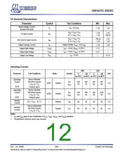
DC Electrical Characteristics
Parameter
Symbol
Test Conditions
Min
Max
Input Leakage Current
(except mode pins)
I
V = 0 to V
IN DD
–1 uA
1 uA
IL
V
≥ V ≥ V
IN
–1 uA
–1 uA
1 uA
100 uA
DD
IH
IH
I
ZZ Input Current
IN1
0 V ≤ V ≤ V
IN
V
≥ V ≥ V
IN
–100 uA
–1 uA
1 uA
1 uA
DD
IL
IL
I
SCD and ZQ Input Current
IN2
0 V ≤ V ≤ V
IN
I
Output Disable, V
= 0 to V
DD
Output Leakage Current
Output High Voltage
Output High Voltage
Output Low Voltage
–1 uA
1.7 V
2.4 V
—
1 uA
—
OL
OUT
DDQ
DDQ
V
I
I
= –8 mA, V
= –8 mA, V
= 2.375 V
= 3.135 V
OH2
OH
OH
V
—
OH3
V
I
= 8 mA
OL
0.4 V
OL
Operating Currents
-250
0
-225
Parameter
Test Conditions
Mode
Symbol
Unit
–40
0
–40
to 70°C to 85°C to 70°C to 85°C
Device Selected;
All other inputs
≥V or ≤ V
Operating
Current
I
355
75
365
75
325
65
335
65
DD
mA
(x72)
(x72)
Pipeline
Pipeline
I
IH
IL
DDQ
3.3 V
Output open
Device Selected;
All other inputs
≥V or ≤ V
Operating
Current
I
355
55
365
55
325
50
3235
50
DD
mA
I
IH
IL
DDQ
2.5 V
Output open
Standby
Current
ZZ ≥ V – 0.2 V
I
mA
mA
—
—
Pipeline
Pipeline
20
85
30
90
20
80
30
85
DD
SB
Device Deselected;
All other inputs
≥ V or ≤ V
Deselect
Current
I
DD
IH
IL
Notes:
1.
2. All parameters listed are worst case scenario.
I
and I
apply to any combination of V , V , V
, and V operation.
DDQ2
DD
DDQ
DD3 DD2 DDQ3
Rev: 1.03 7/2004
12/25
© 2002, GSI Technology
Specifications cited are subject to change without notice. For latest documentation see http://www.gsitechnology.com.

 GSI [ GSI TECHNOLOGY ]