COTS EQUIVALENT
MIL-DTL-38999 Series IV, Breech Coupling
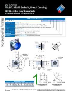
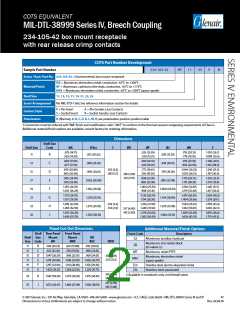
234-105-42 box mount receptacle
with rear release crimp contacts
COTS Part Number Development
Sample Part Number
234ꢀ105ꢀ42
NF
11
ꢀ35
P
N
Series / Basic Part No. 234-105-42 = Environmental, box mount receptacle
ME = Aluminum, electroless nickel, conductive, -ꢀꢁ°C to +ꢂꢃꢃ°C
Material/Finish
NF = Aluminum, cadmium olive drab, conductive, -ꢀꢁ°C to +ꢄꢅꢁ°C
MA† = Aluminum, electroless nickel, conductive, -ꢀꢁ°C to +ꢂꢃꢃ°C (space-grade)
Shell Size
11, 13, 15, 17, 19, 21, 23, 25
Insert Arrangement
Per MIL-STD-ꢄꢁꢀꢃ; See reference information section for details
P = Pin Insert
S = Socket Insert
A = Pin Gender, Less Contacts
B = Socket Gender, Less Contacts
Contact Style
Polarization
N (Normal), A, B, C, D, K, L, M, R; see polarization position position table
† Connectors must be ordered with “MA”finish and modification code “-186T”to conform to the thermal vacuum outgassing requirements of Class G.
Additional material/finish options are available, consult factory for ordering information.
Dimesions
Shell Size
Shell Size
Code
ØA
B Bsc
C
ØD
ØF
ØJ
ØK
S
.579 (14.71)
.563 (14.30)
.535 (13.59)
.520 (13.21)
.793 (20.15)
.778 (19.76)
1.051 (26.7)
1.008 (25.6)
11
B
.812 (20.62)
.509 (12.93)
.693 (17.60)
.677 (17.20)
.650 (16.51)
.634 (16.10)
.919 (23.35)
.904 (22.96)
1.146 (29.1)
1.102 (28.0)
13
15
17
C
D
E
.906 (23.02)
.969 (24.61)
1.062 (26.98)
1.156 (29.36)
1.250 (31.76)
1.375 (34.93)
1.500 (38.10)
.634 (16.10)
.759 (19.28)
.885 (22.48)
1.009 (25.63)
1.134 (28.80)
1.259 (31.98)
1.384 (35.15)
.819 (20.80)
.803 (20.40)
.102 (2.6)
.083 (2.1)
.772 (19.61)
.756 (19.20)
1.044 (26.52)
1.029 (26.13)
1.240 (31.5)
1.197 (30.4)
.138 (3.50)
.122 (3.10)
.945 (24.00)
.929 (23.60)
.898 (22.81)
.882 (22.40)
1.170 (29.72)
1.115 (28.33)
1.335 (33.9)
1.291 (32.8)
1.051 (26.70)
1.035 (26.29)
1.004 (25.50)
.988 (25.10)
1.294 (32.87)
1.279 (32.48)
1.461 (37.1)
1.417 (36.0)
19
21
23
25
F
1.173 (29.79)
1.157 (29.39)
1.130 (28.70)
1.114 (28.30)
1.419 (36.05)
1.404 (35.66)
1.583 (40.2)
1.539 (39.1)
G
H
J
1.299 (32.99)
1.283 (32.59)
.134 (3.4)
.114 (2.9)
1.256 (31.90)
1.240 (31.50)
1.544 (39.22)
1.332 (33.83)
1.709 (43.4)
1.665 (42.3)
.157 (4.00)
.142 (3.60)
1.425 (36.20)
1.409 (35.79)
1.378 (35.00)
1.362 (34.59)
1.669 (42.40)
1.654 (42.01)
1.835 (46.6)
1.791 (45.5)
Panel Cut-Out Dimesions
Shell Rear Panel Front Panel
Additional Material/Finish Options
Description
Finish Code
Shell Size
Size Code
Mount
ØK
Mount
ØKK
BB
BSC
G2
Aluminum, anodize, hardcoat
ØDD
Aluminum, zinc nickel, black
(tri-valent cr)
ZR
11
13
15
17
19
21
B
C
D
E
.796 (20.22)
.922 (23.42)
1.047 (26.59)
1.219 (30.96)
1.297 (32.94)
1.422 (36.12)
.625 (15.88)
.750 (19.05)
.906 (23.01)
1.016 (25.81)
1.141 (28.98)
1.266 (32.16)
.812 (20.62)
.906 (23.01)
.969 (24.61)
1.062 (26.97)
1.156 (29.36)
1.250 (31.75)
MT
Aluminum, nickel PTFE
.133 (3.38)
.123 (3.12)
Aluminum, electroless nickel
(space-grade)
MA†
F
ZL‡
Z1‡
Stainless steel, electro-deposited nickel
Stainless steel, passivated
G
.159 (4.04)
.149 (3.78)
‡ Available in receptacle only, not firewall rated.
23
25
H
J
1.547 (39.29)
1.672 (42.47)
1.375 (34.92)
1.484 (37.69)
1.375 (34.92)
1.500 (38.10)
.155 (3.94)
.145 (3.68)
© 2017 Glenair, Inc • 1211 Air Way, Glendale, CA 91201 • 818-247-6000 • www.glenair.com • U.S. CAGE code 06324 • MIL-DTL-38999 Series III and IV
Dimensions in inches (millimeters) are subject to change without notice
47
Rev. 04.04.18

 GLENAIR [ Glenair ]