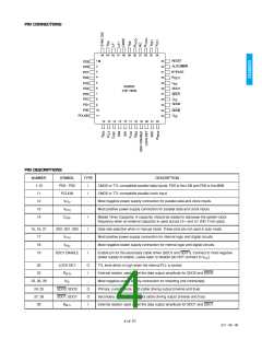
PIN DESCRIPTIONS
NUMBER
31
SYMBOL
TYPE
DESCRIPTION
When high, the SMPTE Scrambler and NRZ encoder are bypassed.
Autostandard or manual mode selectable operation.
Resets the scrambler when asserted.
BYPASS
AUTO/MAN
RESET
VCC1
I
I
I
-
-
I
I
-
I
32
33
34
Most positive power supply connection for analog circuits.
Most negative power supply connection for analog circuits.
Differential VCO current setting resistor that sets the VCO frequency.
No Connect.
35
VEE1
36, 38
37
RVCO+, RVCO
NC
-
39, 43
40
VEE
Most negative power supply connection (substrate).
LBWC
TTL level loop bandwidth control that adjusts the PLL bandwidth to optimize for lowest
jitter. If the pin is set to ground the loop bandwidth is BWMIN. If the pin is left floating, the
loop bandwidth is approximately 3 BWMIN, if the pin is tied to VCC the loop bandwidth is
approximately10 BWMIN
41, 42
44
LF+, LF-
I
I
Differential loop filter pins to optimize loop transfer performance at low loop bandwidths
(NC if not used).
SYNC DIS
Sync detect disable. Logic high disables sync detection. Logic low allows 8 bit operation
by mapping 000-003 to 000 and 3FC-3FF to 3FF.
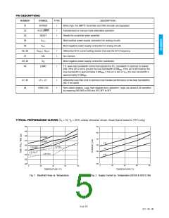
TYPICAL PERFORMANCE CURVES (VS = 5V, TA = 25°C unless otherwise shown. Guard band tested to 70°C only.)
500
490
480
470
460
450
440
430
420
155
150
145
140
135
130
125
4.75 RISE
5.0 RISE
5.25
5.0
5.0 FALL
5.25 RISE
4.75 FALL
5.25 FALL
4.75
0
20
40
60
80
0
20
40
TEMPERATURE (˚C)
60
80
TEMPERATURE (˚C)
Fig. 1 Rise/Fall Times vs. Temperature
Fig. 2 Supply Current vs. Temperature (SDO0 & SDO1 ON)
5 of 10
521 - 96 - 09

 GENNUM [ GENNUM CORPORATION ]