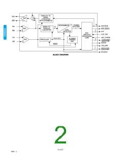
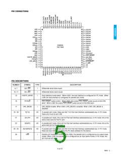
PIN DESCRIPTIONS
NUMBER
SYMBOL
TYPE
DESCRIPTION
27
A/D
CS
I
Parallel port address/data bus control. When HIGH, the parallel port is used for address input.
When LOW, the parallel port is used for data input or output. In I²C mode, this pin must be set
LOW.
28
I
Parallel port chip select. When CS is LOW and R/W is HIGH, the GS9020A drives the address/
data bus. When CS is LOW and R/W is LOW, the user should drive the address/data bus.
When CS is HIGH, the address/data bus is in a high impedance state (Hi - Z). In I²C mode, this
pin must be set HIGH.
31
RESET
STD[3:0]
FL[4:0]
S[1:0]
I
Reset. When LOW, the internal control circuitry is reset.
Video standards indication as described in section 1.4
EDH flag data port to allow access to the EDH flags.
32 - 35
36 - 40
41, 42
O
I/O
I/O
Control bits which select whether FF, AP, or ANC EDH flags are active on the EDH flag data
port (FL[4:0]). In FLAG_MAP mode, the S[1:0] pins become outputs (see device description).
43
44
F_R/W
I
Flag port read/write control. When HIGH, FL[4:0] are configured as outputs allowing EDH flags
to be read from the device. When LOW, FL[4:0] are configured as inputs allowing EDH flags to
be overwritten in the outgoing EDH packet. In FLAG_MAP mode this pin must be set HIGH.
INTERRUPT
O
Interrupt output. This output goes low when EDH errors occur. This pin is an open drain output
and requires an external pullup resistor. If this output is not used, a pullup resistor is not
required.
45
46
47
FLYWDIS
NO_EDH
I
Flywheel disable. When HIGH, the internal flywheel is disabled. When LOW, the internal
flywheel is enabled.
O
O
No EDH present indication. When HIGH, indicates EDH packets are not present in the
incoming data stream.
FIFO_RESET
FIFO Reset output. Asserted LOW during the TRSID word for composite standards and the
EAV or SAV word for component standards.
48
52-60,49
61
PCLKOUT
DOUT[9:0]
V
O
O
O
O
O
I
Parallel clock output.
Parallel digital video data outputs.
Vertical sync indication.
62
H
Horizontal sync indication.
Field indication. F2 is the MSB.
63 - 65
66
F[2:0]
FLAG_MAP
FLAG_MAP mode enable. When HIGH, FLAG_MAP mode is enabled.
When LOW, FLAG_MAP mode is disabled.
70, 71
73
SDO/SDO
O
I
Differential serial data outputs.
VBLANKS/L
Vertical blanking interval control. For NTSC signals, when VBLANKS/L is set LOW the 19 line
blanking interval is selected and when set HIGH the 9 line blanking interval is selected. For
PAL D2 signals, when VBLANKS/L is set LOW the 17 line blanking interval is selected and
when set HIGH the 7 line blanking interval is selected. For PAL component signals VBLANKS/L
should be set LOW.
74
75
BYPASS_EDH
SDOMODE
I
I
Bypass EDH control. When HIGH, the device allows the EDH packet to pass through
unaltered.
Serial data output control. When LOW, the serial data output is re-serialized processed data.
When HIGH, the serial data output is the looped through serial input. After changing
SDOMODE, the GS9020A must be reset for proper operation.
76
77
BLANK_EN
I
I
Blanking enable. When LOW, incoming data words are set to appropriate blanking levels.
Ancillary checksum updating enable. When HIGH, ancillary checksum updating is enabled.
ANC_CHKSM
6 of 31
19922 - 3

 GENNUM [ GENNUM CORPORATION ]