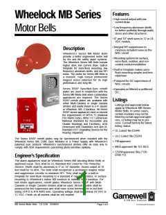
Ordering Information
NOMINAL
VOLTAGE
(VDC)
AVERAGE CURRENT
(amps) @ LISTED
VDC
MODEL
STROBE
INPUT
MODEL
SHELL
INPUT
NUMBER
CANDELA
VOLTAGE
(VDC)
12
NUMBER
SIZE
CURRENT
RSSP-24MCW-FR
RSSP-241575W-FR
RSSP-121575W-FR
24
24
12
15/30/75/110
15 (75 on axis)
15 (75 on axis)
.050/.081/.133/.161
MB-G6-12-R
MB-G6-24-R
MB-G10-12-R 10"
MB-G10-24-R 10"
NOTES:
6"
6"
0.060
0.030
0.060
0.030
0.065
0.170
24
12
24
1. Mounting options are: D,E,Z
2. Average current per actual Wheelock product testing at listed VDC.
For rated average and peak current across UL regulated voltage range
for both filtered DC and unfiltered VRMS, see Installation instructions.
1. Typical dBA at 10 feet is 92, measured in an
anechoic chamber.
2.Mounting options are: D,E,J,K,N,R,S,Z
3. For bells at 12 VDC models are UL rated for 9.0 to
15.6 VDC and all 24 VDC models for 18.0 to 31.0
SYNC MODELS/POWER SUPPLY
AVERAGE
INPUT
SM Sync Module is rated for 3.0 amperes @ 24VDC.
M ODEL
M EAN
MOUNTING
VOLTAGE
(VDC)
NUMBER
CURRENT OPTIONS**
@ 24 VDC
DSM Sync Module is rated for 3.0 amperes per circuit. The maximum number of
interconnected DSM modules is twenty (20).
SM-12/24-R
DSM-12/24-R
24
24
.028
.035
W
W
** Refer to mounting options data sheet.
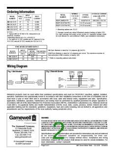
Wiring Diagram
Fig. 1 Bell Models
Fig. 2 Retrofit Strobe
AUDIBLE
STROBE
+
+
-
-
+
-
FROM
TO NEXT
APPLIANCE
OR EOLR
PRECEDING
APPLIANCE OR
FACP
-
-
TO NEXT
FROM
+
+
APPLIANCE
OR END-OF-LINE
}
RESISTOR
PRECEDING
APPLIANCE
OR FACP
{
FROM
TO NEXT
STROBE OR
EOLR
(EOLR)
-
-
PRECEDING
STROBE OR
FACP
+
+
Wheelock products must be used within their published specifications and must be PROPERLY specified, applied, installed,
operated, maintained and operationally tested in accordance with their installation instructions at the time of installation and at
least twice a year or more often and in accordance with local, state and federal codes, regulations and laws. Specification,
application, installation, operation, maintenance and testing must be performed by qualified personnel for proper operation in
accordance with all of the latest National Fire Protection Association (NFPA), Underwriters’ Laboratories (UL), National Electrical
Code (NEC), Occupational Safety and Health Administration (OSHA), local, state, county, province, district, federal and other
applicable building and fire standards, guidelines, regulations, laws and codes including, but not limited to, all appendices and
amendments and the requirements of the local authority having jurisdiction (AHJ).
WARNING
PLEASE READ THESE SPECIFICATIONSANDASSOCIATED INSTALLATION INSTRUCTIONS
CAREFULLY BEFORE USING, SPECIFYING ORAPPLYING THIS PRODUCT. FAILURE TO COM-
PLY WITH ANY OF THESE INSTRUCTIONS, CAUTIONS OR WARNINGS COULD RESULT IN
The Gamewell Company
12 Clintonville Road
IMPROPERAPPLICATION, INSTALLATIONAND/OR OPERATION OF THESE PRODUCTS INAN
EMERGENCY SITUATION, WHICH COULD RESULT IN PROPERTY DAMAGE, AND SERIOUS
INJURY OR DEATH TO YOUAND/OR OTHERS.
Northford, CT 06472-1610
Phone: 203-484-7161
Fax: 203-484-7118
Specifications and wiring information are provided for information only and are believed
to be accurate. Gamewell assumes no responsibility for their use.
Data and design are subject to change without notice. Installation and wiring
instructions shipped with the product shall always be used for actual installation. For
more information, contact Gamewell.
www.gamewell.com
A Honeywell Company
© 2004 Gamewell
Page 2 of 2
MB Series Motor Bells CS-2236 05/04/04

 GAMEWELL-FCI [ GAMEWELL-FCI BY HONEYWELL ]