MB3773
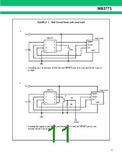
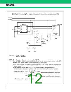
EXAMPLE 4 : Montitoring Two Supply Voltages (with hysterisis, reset output and NMI)
VCC2(12V)
VCC1 (5V)
Logic circuit
MB3773
RESET
RESET
CK
1
2
3
4
8
7
6
5
CT
100k
R3
NMI or port
GND
180k
10k
R6
R4
+
+
_
_
Comp. 1
1.2k
R1
Comp. 2
5.1k
R2
4.7k
R5
Example
: Comp. 1, Comp. 2
: MB4204, MB47393
NOTE: The 5V supply voltage is monitored by the MB3773.
The 12V supply viltage is monitored by the external circuit. Its output is connected to the NMI
pin and, when voltage drops, Comp. 2 interrrupts the logic circuit.
• Use VCC1 (=5V) to power the comparators (Comp. 1 and Comp. 2) in the external circuit
shown above.
• The detection voltage of the VCC2 (=12V) supply voltage is approximately 0.2V.
VCC2 detection voltage and hysterisis width can be found using the following formulas:
R3 + (R4 // R5)
→
Detection voltage
× V
REF
V2H =
R4 // R5
R3 + R5
(Approx. 9.4V in the above illustration)
(Approx. 9.2V in the above illustration)
V2L =
× VREF
R5
→
HYS
2H
2L
Hysterisis width
V
= V - V
12

 FUJITSU [ FUJITSU ]