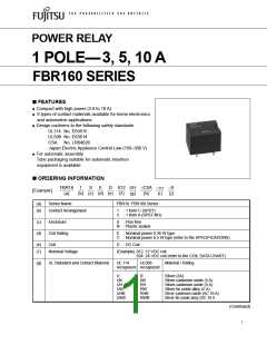
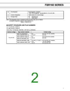
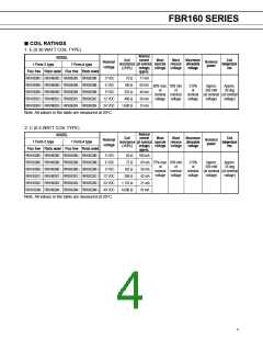
FBR160 SERIES
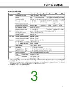
■ SPECIFICATIONS
Item
—
-K
1 form C or 1 form A, single contact
Silver
Maximum 100 mΩ (silver contact at 0.5 A 6 VDC/other contacts at 1 A 6 VDC)
-H
-W
-HB
-WB
Contact
Arrangement and Style
Material
Silver-cadmium oxide
Silver tin oxide alloy Silver-cadmium oxide Silver tin oxide alloy
Resistance (initial)
Ratings (resistive load)
3 A 120 VAC
3 A 28 VDC
5 A 120 VAC
5 A 28 VAC
5 A 28 VDC
10 A 120 VAC (N.O.)
7 A 120 VAC (N.C.)
10 A 28 VDC
Maximum Carrying Current
Maximum Switching Power
Max. Switching Voltage*1
Minimum Switching Load*2
Nominal Power
5 A
10 A
10 A
140 W
600 VA or 140 W
1,200 VA
280 W
360 VA or 84 W
250 VAC or 125 VDC
0.3 W (30 mA 5 V)
0.3 W (50 mA 5 V)
0.5 W (100 mA 5 V) 0.5 W (100 mA 5 V)
Coil
Approx. 0.36 W (E coil type)/0.5 W (C coil type) (at 20°C)
–30°C to +80°C (no frost) *3
Operating Temperature
Operate Humidity
45 to 85% RH
Time Value Operate (at nominal voltage) Maximum 10 msec
Release (at nominal voltage) Maximum 5 msec
Insulation
Resistance (initial)
Minimum 100 MΩ (at 500 VDC)
Dielectric Between coil and contacts 1,500 VAC 1 minute
Strength
Between open contacts
500 VAC 1 minute
Surge Strength
3,500 V (at 1.2 × 50 µs)
Life
Mechanical
1 × 10 7 operations minimum
1 × 10 5 operations minimum (at contact rating)
1 × 10 5 operations minimum (at contact rating)
10 to 55 Hz (double amplitude of 1.5mm)
100 m/s2 (11 ±1ms)
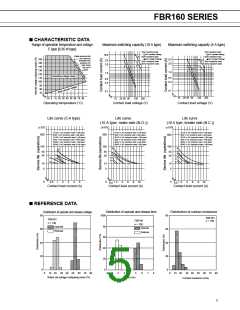
Electrical (refer to
the REFERENCE
DATA)
DC
AC
Other
Vibration Resistance
Shock
No contact opening
Resistance
No damage
1,000 m/m2 (6 ±1ms)
Weight
Approximately 11 g
1
*
If the switching voltage exceeds the rated contact voltage, reduce the current. The current values vary according to the
type of load.
*2 Values when switching a resistive load at normal room temperature and humidity, and in a clean environment. The minimum
switching load varies with the switching frequency and operation environment.
*3 Based on UL Class A coil insulation system.
3

 FUJITSU [ FUJITSU ]