FT4232H QUAD HIGH SPEED USB TO MULTIPURPOSE UART/MPSSE IC
Datasheet
Version 2.4
Document No.: FT_000060 Clearance No.: FTDI#78
3.1.4
Configured Pins
The following sections describe the function of the configurable pins referred to in Table 3.1 which is
determined by how the FT4232H is configured.
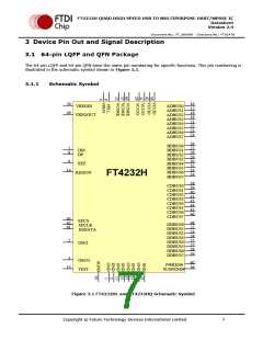
3.1.4.1
FT4232H pins used as an asynchronous serial interface
Any of the 4 channels of the FT4232H can be configured as an asynchronous serial UART interface
(RS232/422/485). When configured in this mode, the pins used and the descriptions of the signals are
shown in Table 3.5.
Channel
A
Channel Channel
Channel
D
B
C
Name
Type
RS232 Configuration Description
Pin No.
Pin No.
Pin No.
Pin No.
16
26
27
28
29
30
32
33
38
39
40
41
43
44
45
48
TXD
RXD
OUTPUT
INPUT
TXD = transmitter output
17
52
RXD = receiver input
18
53
RTS#
CTS#
DTR#
DSR#
DCD#
OUTPUT
INPUT
RTS# = Ready To send handshake output
CTS# = Clear To Send handshake input
19
54
DTR# = Data Transmit Ready modem
signaling line
21
55
OUTPUT
INPUT
DSR# = Data Set Ready modem signaling
line
22
57
DCD# = Data Carrier Detect modem
signaling line
23
58
INPUT
RI# = Ring Indicator Control Input. When
the Remote Wake up option is enabled in
the EEPROM, taking RI# low can be used
to resume the PC USB Host controller
from suspend.
RI#/
TXDEN
24
34
46
59
INPUT/OUTPUT
(see note 1, 2 and 3)
TXDEN = (TTL level). For use with RS485
level converters.
Table 3.5 Channel A,B,C and D Asynchronous Serial Interface Configured Pin Descriptions
Notes
1. When using remote wake-up, ensure the resistors are pulled-up in suspend. Also ensure
peripheral designs do not allow any current sink paths that may partially power the peripheral.
2. If remote wake-up is enabled, a peripheral is allowed to draw up to 2.5mA in suspend. If remote
wake-up is disabled, the peripheral must draw no more than 500uA in suspend.
3. If a Pull-down is enabled, the FT4232H will not wake up from suspend.
Copyright © Future Technology Devices International Limited
11

 FTDI [ FUTURE TECHNOLOGY DEVICES INTERNATIONAL LTD. ]