Freescale Semiconductor, Inc.
Electrical Specifications
5.0-Volt Control Timing
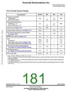
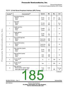
13.9 5.0-Volt Control Timing
(1)
Symbol
Min
Max
Unit
Characteristic
Frequency of operation
f
Crystal option
External clock option
—
dc
4.2
4.2
MHz
OSC
Internal operating frequency
Crystal (f
÷ 2)
f
—
dc
2.1
2.1
MHz
OSC
OP
External clock (f
÷ 2)
OSC
t
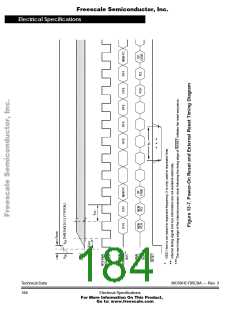
Cycle time (see Figure 13-7)
480
—
—
ns
CYC
t
Crystal oscillator startup time (see Figure 13-7)
100
ms
OXOV
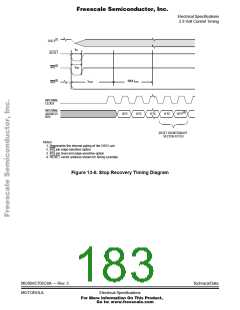
Stop recovery startup time (crystal oscillator)
t
—
8
100
—
ms
ILCH
(see Figure 13-6)
t
t
RESET pulse width (see Figure 13-7)
RL
CYC
Timer
t
t
4.0
125
RESL
—
—
—
CYC
(2)
Resolution
t
, t
ns
TH TL
Input capture pulse width (see Figure 13-5)
Input capture pulse period (see Figure 13-5)
(3)
t
t
CYC
TLTL
Interrupt pulse width low (edge-triggered)
t
125
(4)
—
ns
ILIH
(see Figure 4-2. External Interrupt Timing)
Interrupt pulse period
t
t
—
—
ILIL
CYC
(see Figure 4-2. External Interrupt Timing)
t
, t
OSC1 pulse width
90
ns
OH OL
1. V = 5.0 Vdc ± 10%, V = 0 Vdc; T = T to T
H
DD
SS
A
L
2. Since a 2-bit prescaler in the timer must count four internal cycles (t
the timer resolution.
), this is the limiting minimum factor in determining
CYC
3. The minimum period, t
, should not be less than the number of cycle times it takes to execute the capture interrupt ser-
TLTL
vice routine plus 24 t
.
CYC
4. The minimum period, t , should not be less than the number of cycle times it takes to execute the interrupt service routine
ILIL
plus 19 t
.
CYC
MC68HC705C8A — Rev. 3
MOTOROLA
Technical Data
Electrical Specifications
For More Information On This Product,
Go to: www.freescale.com

 FREESCALE [ Freescale ]