Freescale Semiconductor, Inc.
Resets and Interrupts
10.6 Interrupts
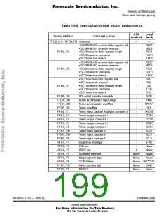
Excluding reset type interrupts, the MC68HC11P2 has 20 interrupt
vectors that support 32 interrupt sources. The 17 maskable interrupts
are generated by on-chip peripheral systems. These interrupts are
recognized when the global interrupt mask bit (I) in the condition code
register (CCR) is clear. The three nonmaskable interrupt sources are
illegal opcode trap, software interrupt, and XIRQ pin. Refer to Table 10-
4, which shows the interrupt sources and vector assignments for each
source.
For some interrupt sources, such as the SCI interrupts, the flags are
automatically cleared during the normal course of responding to the
interrupt requests. For example, the RDRF flag in the SCI system is
cleared by the automatic clearing mechanism consisting of a read of the
SCI status register while RDRF is set, followed by a read of the SCI data
register. The normal response to an RDRF interrupt request would be to
read the SCI status register to check for receive errors, then to read the
received data from the SCI data register. These two steps satisfy the
automatic clearing mechanism without requiring any special
instructions.
10.6.1 Interrupt recognition and register stacking
An interrupt can be recognized at any time after it is enabled by its local
mask, if any, and by the global mask bit in the CCR. Once an interrupt
source is recognized, the CPU responds at the completion of the
instruction being executed. Interrupt latency varies according to the
number of cycles required to complete the current instruction. When the
CPU begins to service an interrupt, the contents of the CPU registers are
pushed onto the stack in the order shown in Table 10-5. After the CCR
value is stacked, the I-bit and the X-bit, if XIRQ is pending, are set to
inhibit further interrupts. The interrupt vector for the highest priority
pending source is fetched, and execution continues at the address
specified by the vector. At the end of the interrupt service routine, the
return from interrupt instruction is executed and the saved registers are
Technical Data
MC68HC11P2 — Rev 1.0
Resets and Interrupts
For More Information On This Product,
Go to: www.freescale.com

 FREESCALE [ Freescale ]