FUNCTIONAL DESCRIPTION
FUNCTIONAL INTERNAL BLOCK DESCRIPTION
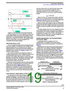
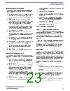
retry timer starts to time out. When the timer expires after
100 ms, the LDO tries to power up again for 10 ms,
repeatedly checking for the overcurrent condition. The
current limit of the LDO can be set by using the following
formula:
ILIM = 50 mV/RS
Where RS is the LDO current sense resistor, connected
between the CS terminal and the LDO terminal output (see
Figure 33 on page 32), and 50 mV is the typical value of the
LDO current sense comparator threshold voltage.
When no current sense resistor is used, it is still possible
to detect the overcurrent condition by tying the current sense
terminal CS to the VBST voltage. In this case, the overcurrent
condition is sensed by saturation of the linear regulator driver
buffer.
The output voltage of the LDO can be adjusted by means
of an external resistor divider connected to the feedback
control terminal LFB. The linear regulator output voltage can
be adjusted in the range of 0.8 V to VIN - LDO dropout
voltage. Power-up, power-down, and fault management are
coordinated with the switching regulator.
Figure 15. LDO Converter Overcurrent Protection
The output voltage VOUT can be adjusted by means of an
external resistor divider connected to the feedback control
terminal INV. The switching regulator output voltage can be
adjusted in the range of 0.8 V to VIN - buck dropout voltage.
Power-up, power-down, and fault management are
coordinated with the linear regulator.
POWER SEQUENCING VOLTAGE MARGINING
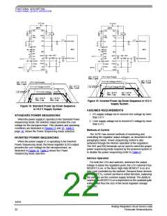
WATCHDOG TIMER
A watchdog function is available via I2C bus
communication. It is possible to select either window
watchdog or time-out watchdog operation, as illustrated in
Figure 16.
SWITCHER OSCILLATOR
A 300 kHz (default) oscillator sets the switching frequency
of the buck regulator. The frequency of the oscillator can be
adjusted between 200 kHz and 400 kHz by an optional
external resistor RF connected from the FREQ terminal of the
integrated circuit to ground. See Figure 6 on page 14 for
frequency resistor selection.
Watchdog time-out starts when the watchdog function is
activated via I2C bus sending a Watchdog Programming
command byte, thus determining watchdog operation
(window or time-out) and period duration (refer to Table 8,
page 27). If the watchdog is cleared by receiving a new
Watchdog Programming command through the I2C bus, the
watchdog timer is reset and the new time-out period begins.
If the watchdog time expires, the RST will become active
(LOW) for a time determined by the RC components of the
RT timer plus 10 ms. After a watchdog time-out, the function
is no longer active.
The CLKSYN terminal can be configured as either an
oscillator output when the CLKSEL terminal is left open or as
a synchronization input when the CLKSEL terminal is
grounded. The oscillator output signal is a square wave logic
signal with 50% duty cycle, 180 degrees out-of-phase with
the internal clock signal. This allows opposite phase
synchronization of two 34702 devices.
Watchdog Closed
Window Open
When the CLKSYN terminal is used as a synchronization
input (CLKSEL terminal grounded), the external resistor RF
chosen from the chart in Figure 6 should be used to
synchronize the internal slope compensation ramp to the
external clock. Operation is only recommended between
200 kHz and 400 kHz. The supplied synchronization signal
does not need to be 50% duty cycle. Minimum pulse width is
1.0 µs.
No Watchdog Clear Allowed
for Watchdog Clear
50% of Watchdog Period
Watchdog Period
Timing Selected via 12C Bus – See Table 4
Window Watchdog
Window Open for Watchdog Clear
LOW DROPOUT LINEAR REGULATOR (LDO)
The adjustable low dropout linear regulator (LDO) is
capable of supplying a 1.0 A output current. It has a current
limit with retry capability. When the voltage measured across
the current sense resistor reaches the 50 mV threshold, the
control circuit limits the current for 10 ms. If the overcurrent
condition still exists, the linear regulator is turned off and the
Watchdog Period
Timing Selected via I2C Bus – See Table 4
Time-Out Watchdog
Figure 16. Watchdog Operation
34701
Analog Integrated Circuit Device Data
Freescale Semiconductor
19

 FREESCALE [ Freescale ]