Inrush Current Limiters In Switching
Power Supplies
~
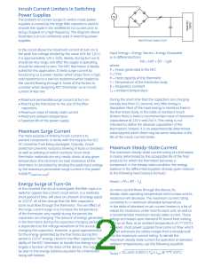
The problem of current surges in switch-mode power
supplies is caused by the large filter capacitors used to
smooth the ripple in the rectified 60 Hz current prior to
being chopped at a high frequency. The diagram above
illustrates a circuit commonly used in switching power
supplies.
Typical Power Supply Circuit
In the circuit above the maximum current at turn-on is
the peak line voltage divided by the value of R; for 120 V,
it is approximately 120 x √2/RI. Ideally, during turn-on RI
should be very large, and after the supply is operating,
should be reduced to zero. The NTC thermistor is ideally
suited for this application. It limits surge current by
functioning as a power resistor which drops from a high
cold resistance to a low hot resistance when heated by
the current flowing through it. Some of the factors to
consider when designing NTC thermistor as an inrush
current limiter are:
Input Energy = Energy Stored + Energy Dissipated
or in differential form:
Pdt = HdT + δ(T – TA)dt
where:
P = Power generated in the NTC
t = Time
H = Heat capacity of the thermistor
T = Temperature of the thermistor body
δ = Dissipation constant
TA = Ambient temperature
During the short time that the capacitors are charging
(usually less than 0.1 second), very little energy is
dissipated. Most of the input energy is stored as heat in
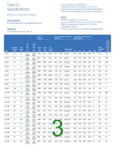
the thermistor body. In the table of standard inrush
limiters there is listed a recommended value of maximum
capacitance at 120 V and 240 V. This rating is not
intended to define the absolute capabilities of the
thermistors; instead, it is an experimentally determined
value beyond which there may be some reduction in the
life of the inrush current limiter.
• Maximum permissible surge current at turn-on
• Matching the thermistor to the size of the filter
capacitors
• Maximum value of steady state current
• Maximum ambient temperature
• Expected life of the power supply
Maximum Surge Current
The main purpose of limiting inrush current is to
prevent components in series with the input to the DC/
DC convertor from being damaged. Typically, inrush
protection prevents nuisance blowing of fuses or breakers
as well as welding of switch contacts. Since most
thermistor materials are very nearly ohmic at any given
temperature, the minimum no-load resistance of the
thermistor is calculated by dividing the peak input voltage
by the maximum permissible surge current in the power
supply (Vpeak/Imax surge).
Maximum Steady-State Current
The maximum steady-state current rating of a thermistor
is mainly determined by the acceptable life of the final
products for which the thermistor becomes a
component. In the steady-state condition, the energy
balance in the differential equation already given reduces
to the following heat balance formula:
Power = I2R = δ(T – TA)
Energy Surge at Turn-On
At the moment the circuit is energized, the filter caps in a
switcher appear like a short circuit which, in a relatively
short period of time, will store an amount of energy equal
to 1/2CV2. All of the charge that the filter capacitors
store must flow through the thermistor. The net effect of
this large current surge is to increase the temperature
of the thermistor very rapidly during the period the
capacitors are charging. The amount of energy generated
in the thermistor during this capacitor-charging period
is dependent on the voltage waveform of the source
charging the capacitors. However, a good approximation
for the energy generated by the thermistor during this
period is 1/2CV2 (energy stored in the filter capacitor). The
ability of the NTC thermistor to handle this energy surge is
largely a function of the mass of the device. This logic can
be seen in the energy balance equation for a thermistor
being self-heated:
As more current flows through the device, its
steady-state operating temperature will increase and its
resistance will decrease. The maximum current rating
correlates to a maximum allowable temperature.
In the table of standard inrush current limiters is a list of
values for resistance under load for each unit, as well as
a recommended maximum steady-state current. These
ratings are based upon standard PC board heat sinking,
with no air flow, at an ambient temperature of 77° (25°C).
However, most power supplies have some air flow, which
further enhances the safety margin that is already built
into the maximum current rating. To derate the
maximum steady state current for operation at elevated
ambient temperatures, use the following equation:
Iderated = √(1.1425–0.0057 x TA) x Imax @ 77°F (25°C)

 FREESCALE [ Freescale ]