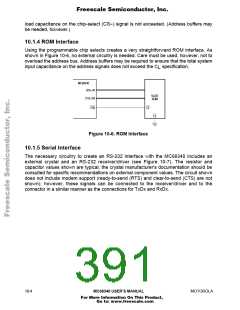
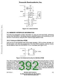
Freescale Semiconductor, Inc.
Additionally, the relationship between the asynchronous inputs and the clock edge, as
shown in Figure 10-11, does not change as frequency changes.
A second type of specification indicates the minimum amount of time a signal will be
asserted. This type of specification is illustrated in Figure 10-12.
T/2
N
CLKOUT
OUTPUT
t
d
t
w
Figure 10-12. Signal Width Specifications
The method for calculating a frequency-adjusted t is as follows:
w
t ' = t + N (T '/2 – T /2) + (T '/2 – t )
w
w
f
f
f
d
where:
t ' = the frequency-adjusted signal width
w
t = the signal width at 16.78 MHz
w
N = the number of full one-half clock periods in t
w
T '/2 = one-half the new clock period
f
T /2 = one-half the clock period at full speed
f
t = the propagation time from the clock edge
d
The following calculation uses a 16.78-MHz part, specification 14, AS width asserted, at
12.5 MHz as an example:
t = 100 ns
w
N = 3
T '/2 = 80/2 = 40 ns
f
T /2 = 60/2 = 30 ns
f
t = 30 ns maximum
d
therefore:
t ' = 100 + 3(40 – 30) + (40 – 30) = 140 ns
w
The third type of specification used is a skew between two outputs (see Figure 10-13).
10-8
MC68340 USER’S MANUAL
MOTOROLA
For More Information On This Product,
Go to: www.freescale.com

 FREESCALE [ Freescale ]