Freescale Semiconductor, Inc.
5.6.2.8.16 Future Commands. Unassigned command opcodes are reserved by Motorola
for future expansion. All unused formats within any revision level will perform a NOP and
return the ILLEGAL command response.
5.6.3 Deterministic Opcode Tracking
The CPU32 utilizes deterministic opcode tracking to trace program execution. Two
signals, IPIPE and IFETCH, provide all information required to analyze instruction pipeline
operation.
5.6.3.1 INSTRUCTION FETCH (IFETCH). IFETCH indicates which bus cycles are
accessing data to fill the instruction pipeline. IFETCH is pulse-width modulated to
multiplex two indications on a single pin. Asserted for a single clock cycle, IFETCH
indicates that the data from the current bus cycle is to be routed to the instruction pipeline.
IFETCH held low for two clock cycles indicates that the instruction pipeline has been
flushed. The data from the bus cycle is used to begin filling the empty pipeline. Both user
and supervisor mode fetches are signaled by IFETCH.
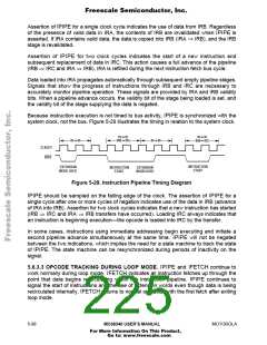
Proper tracking of bus cycles via IFETCH on a fast bus requires a simple state machine.
On a two-clock bus, IFETCH may signal a pipeline flush with associated prefetch followed
immediately by a second prefetch. That is, IFETCH remains asserted for three clocks, two
clocks indicating the flush/fetch and a third clock signaling the second fetch. These two
operations are easily discerned if the tracking logic samples IFETCH on the two rising
edges of CLKOUT, which follow the AS (DS during show cycles) falling edge. Three-clock
and slower bus cycles allow time for negation of the signal between consecutive
indications and do not experience this operation.
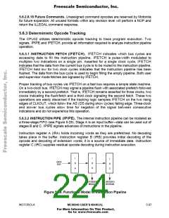
5.6.3.2 INSTRUCTION PIPE (IPIPE). The internal instruction pipeline can be modeled as
a three-stage FIFO (see Figure 5-28). Stage A is an input buffer—data can be used out of
stages B and C. IPIPE signals advances of instructions in the pipeline.
Instruction register A (IRA) holds incoming words as they are prefetched. No decoding
takes place in the buffer. Instruction register B (IRB) provides initial decoding of the
opcode and decoding of extension words; it is a source of immediate data. Instruction
register C (IRC) supplies residual opcode decoding during instruction execution.
I
I
I
DATA
BUS
R
R
B
R
C
A
EXTENSION
WORDS
OPCODES
RESIDUAL
Figure 5-28. Functional Model of Instruction Pipeline
MOTOROLA
MC68340 USER’S MANUAL
5- 87
For More Information On This Product,
Go to: www.freescale.com

 FREESCALE [ Freescale ]