Product Specification
Highly Integrated Green-Mode PWM Controller
SG5841/J
OPERATION DESCRIPTION
Start-up Current
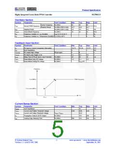
Current Sensing / PWM Current Limiting
Peak-current-mode control is utilized in SG5841/J to
regulate output voltage and provide pulse-by-pulse
current limiting. The switch current is detected by a sense
resistor into the SENSE pin. The PWM duty cycle is
determined by this current sense signal and the feedback
voltage. When the voltage on the SENSE pin reaches
around VCOMP = (VFB–1.0)/3.2, a switch cycle is
terminated immediately. VCOMP is internally clamped to a
variable voltage around 0.85V for output power limit.
Typical start-up current is only 14µA, so that a high
resistance and low-wattage start-up resistor can be used to
minimize power loss. For an AC/DC adapter with
universal input range, a 1.5MΩ, 0.25W start-up resistor
and a 10µF/25V VDD hold-up capacitor are enough for
this application.
Operating Current
Operating current is around 4mA. The low operating
current enables better efficiency and reduces the
requirement of VDD hold-up capacitance.
Leading-Edge Blanking
Each time the power MOSFET is switched on, a turn-on
spike occurs at the sense-resistor. To avoid premature
termination of the switching pulse, a leading-edge
blanking time is built in. During this blanking period, the
current-limit comparator is disabled and cannot switch off
the gate drive.
Green-Mode Operation
The proprietary green-mode function provides off-time
modulation to continuously decrease the PWM frequency
under light-load conditions. To avoid acoustic noise
problems, the minimum PWM frequency is set above
22kHz. This green-mode function dramatically reduces
power consumption under light-load and zero-load
conditions. Power supplies using a SG5841/J controller
can meet even the most restrictive international
regulations regarding standby power consumption.
Under-Voltage Lockout (UVLO)
The turn-on and turn-off thresholds of SG5841/J are fixed
internally at 16V/10V. During start-up, the hold-up
capacitor must be charged to 16V through the start-up
resistor for the IC to be enabled. The hold-up capacitor
continues to supply VDD before the energy can be
delivered from auxiliary winding of the main transformer.
Oscillator Operation
VDD must not drop below 10V during this start-up process.
A resistor connected from the RI pin to the GND pin
generates a constant current source for the SG5841/J
controller. This current is used to determine the center
PWM frequency. Increasing the resistance reduces PWM
frequency. Using a 26KΩ resistor, RI, results in a
corresponding 65KHz PWM frequency. The relationship
between RI and the switching frequency is:
This UVLO hysteresis window ensures that hold-up
capacitor is adequate to supply VDD during start-up.
Gate Output / Soft Driving
The SG5841/J BiCMOS output stage is a fast totem pole
gate driver. Cross conduction has been avoided to
minimize heat dissipation, increase efficiency, and
enhance reliability. The output driver is clamped by an
internal 18V Zener diode to protect power MOSFET
transistors against undesirable gate over-voltage. A soft
driving waveform is implemented to minimize EMI.
1690
----------------------------
(KHz)
(1)
fPWM =
RI (KΩ)
The range of the PWM oscillation frequency is designed
as 47KHz ~ 109KHz.
Built-in Slope Compensation
The sensed voltage across the current-sense resistor is
used for peak-current-mode control and pulse-by-pulse
current limiting. Built-in slope compensation improves
stability or prevents sub-harmonic oscillation. SG5841/J
inserts a synchronized, positive-going ramp at every
switching cycle.
SG5841J also integrates frequency hopping function
internally. The frequency variation ranges from around
62KHz to 68KHz for a center frequency of 65KHz. The
frequency hopping function helps reduce EMI emission of
a power supply with minimum line filters.
© System General Corp.
Version 1.3.1 (IAO33.0017.B6)
- 9 -
www.sg.com.tw • www.fairchildsemi.com
September 20, 2007

 FAIRCHILD [ FAIRCHILD SEMICONDUCTOR ]