Product Specification
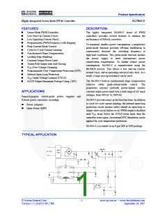
Highly Integrated Green-Mode PWM Controller
SG5841/J
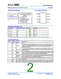
MARKING DIAGRAMS
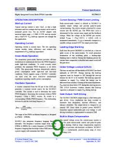
PIN CONFIGURATION
H: J = with Frequency Hopping
GND
FB
GATE
VDD
Null = without Frequency
Hopping
T: D = DIP, S = SOP
P: Z = Lead Free
SG5841HTP
XXXXXXXXYWWV
Null=regular package
XXXXXXXX: Wafer Lot
Y: Year; WW: Week
V: Assembly Location
VIN
RI
SENSE
RT
ORDERING INFORMATION
Part Number
Frequency Hopping Pb-Free
Package
SG5841JSZ
Yes
Yes
No
8-Pin SOP
8-Pin DIP
8-Pin SOP
8-Pin DIP
SG5841JDZ
SG5841SZ
SG5841DZ
No
PIN DESCRIPTIONS
Pin No. Symbol Function
Description
1
GND
Ground
Ground.
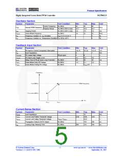
The signal from the external compensation circuit is fed into this pin. The PWM duty cycle is
determined in response to the signal from this pin and the current-sense signal from Pin 6. If FB
voltage exceeds the threshold, the internal protection circuit disables PWM output after a
predetermined delay time.
2
FB
Feedback
For start-up, this pin is pulled high to the rectified line input via a resistor. Since the start-up
3
4
VIN
RI
Start-Up Input current requirement of the SG5841/J is very small, a large start-up resistance can be used to
minimize power loss.
A resistor connected from the RI pin to GND pin provides the SG5841/J with a constant current
source. This determines the center PWM frequency. Increasing the resistance reduces PWM
frequency. Using a 26KΩ resistor results in a 65KHz center PWM frequency.
Reference
Setting
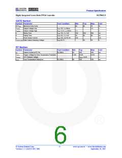
For over-temperature protection. An external NTC thermistor is connected from this pin to the
GND pin. The impedance of the NTC decreases at high temperatures. Once the voltage of the
RT pin drops below a fixed limit, PWM output is disabled.
Temperature
Detection
5
6
RT
Current sense. The sensed voltage is used for peak-current-mode control and cycle-by-cycle
SENSE
Current Sense
current limiting.
7
8
VDD
Power Supply Power supply. If VDD exceeds a threshold, the internal protection circuit disables PWM output.
GATE
Driver Output
The totem-pole output driver for the power MOSFET, which is internally clamped below 18V.
© System General Corp.
Version 1.3.1 (IAO33.0017.B6)
- 2 -
www.sg.com.tw • www.fairchildsemi.com
September 20, 2007

 FAIRCHILD [ FAIRCHILD SEMICONDUCTOR ]