Product Specification
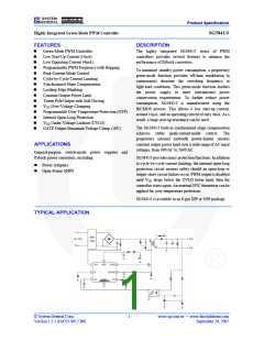
Highly Integrated Green-Mode PWM Controller
SG5841/J
Oscillator Section
Symbol
Parameter
Test Condition
RI=26KΩ
Min.
62
Typ.
65
Max.
68
Unit
Center Frequency
Hopping Range
FOSC
Normal PWM Frequency
KHz
RI=26KΩ (5841J only)
RI=26KΩ (5841J only)
RI=26KΩ
±3.7
3.9
±4.2
4.4
±4.7
4.9
25
tHOP
FOSC-G
FDV
Hopping Period
ms
KHz
%
Green-Mode Frequency
18
22
Frequency Variation vs. VDD Deviation
VDD=11.5V to 24.7V
5
FDT
Frequency Variation vs. Temperature Deviation TA=-20 to +85°C
5
%
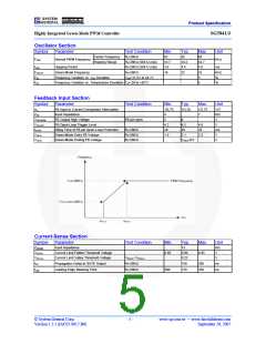
Feedback Input Section
Symbol
AV
Parameter
FB Input to Current Comparator Attenuation
Test Condition
Min.
1/3.75
4
Typ.
1/3.20
Max.
1/2.75
7
Unit
V/V
KΩ
V
ZFB
Input Impedance
VFB-OPEN
VFB-OLP
tD-OLP
FB Output High Voltage
FB pin open
5
6
FB Open-Loop Trigger Level
Delay Time of FB pin Open-Loop Protection
Green-Mode Entry FB Voltage
Green-Mode Ending FB Voltage
4.2
26
4.5
4.8
32
V
RI=26KΩ
RI=26KΩ
RI=26KΩ
29
ms
V
VFB-N
1.9
2.1
2.3
VFB-G
VFB-N-0.5
V
Current-Sense Section
Symbol
ZSENSE
Parameter
Input Impedance
Test Condition
Min.
Typ.
12
Max.
Unit
KΩ
V
VSTHFL
Current Limit Flatten Threshold Voltage
Current Limit Valley Threshold Voltage
0.85
0.90
0.22
0.95
VSTHVA
VSTHFL–VSTHVA
V
tPD
Propagation Delay to GATE Output
Leading-Edge Blanking Time
RI=26KΩ
150
270
200
350
ns
ns
tLEB
RI=26KΩ
200
© System General Corp.
Version 1.3.1 (IAO33.0017.B6)
- 5 -
www.sg.com.tw • www.fairchildsemi.com
September 20, 2007

 FAIRCHILD [ FAIRCHILD SEMICONDUCTOR ]