KA79XX/KA79XXA
Typical Applications
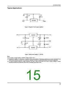
1uF
2.2uF
+
+
Co
C
I
1
2
3
KA79XX
Input
Output
Figure 6. Negative Fixed output regulator
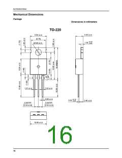
1
3
+15V
+12V
KA7812
+
+
2
Co
1N4001
C1
0.33uF
*
*
1uF
GND
+
2.2uF
1uF
+
1N4001
C1
Co
1
2
3
-12V
-15V
KA7912
Figure 7. Split power supply ( ± 12V/1A)
Note:
(1) To specify an output voltage, substitute voltage value for "XX "
(2) Required for stability. For value given, capacitor must be solid tantalum. If aluminium electronics are used, at least ten times
value shown should be selected. C is required if regulator is located an appreciable distance from power supply filter.
I
(3) To improve transient response. If large capacitors are used, a high current diode from input to output (1N400l or similar)
should be introduced to protect the device from momentary input short circuit.
15

 FAIRCHILD [ FAIRCHILD SEMICONDUCTOR ]