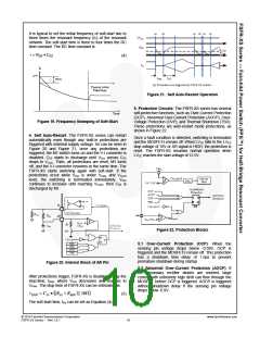
5.3 Over-Voltage Protection (OVP): When the LVCC
reaches 23V, OVP is triggered. This protection is used
when auxiliary winding of the transformer to supply VCC
to the FPS™ is utilized.
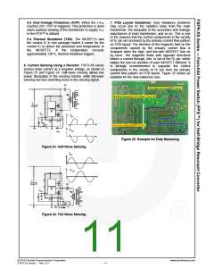
7. PCB Layout Guidelines: Duty imbalance problems
may occur due to the radiated noise from the main
transformer, the inequality of the secondary side leakage
inductances of main transformer, and so on. This is one
of the reasons that the control components in the vicinity
of RT pin are enclosed by the primary current flow pattern
on PCB layout. The direction of the magnetic field on the
components caused by the primary current flow is
changed when the high- and low-side MOSFET turn on
by turns. The magnetic fields with opposite directions
induce a current through, into, or out of the RT pin, which
makes the turn-on duration of each MOSFET different. It
is strongly recommended to separate the control
components in the vicinity of RT pin from the primary
current flow pattern on PCB layout. Figure 25 shows an
example for the duty-balanced case.
5.4 Thermal Shutdown (TSD): The MOSFETs and
the control IC in one package makes it easier for the
control IC to detect the abnormal over-temperature of
the MOSFETs. If the temperature exceeds
approximately 130°C, thermal shutdown triggers.
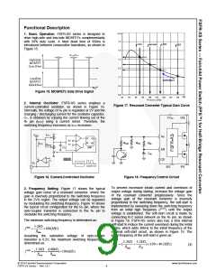
6. Current Sensing Using a Resistor: FSFR-XS series
senses drain current as a negative voltage, as shown in
Figure 23 and Figure 24. Half-wave sensing allows low
power dissipation in the sensing resistor, while full-wave
sensing has less switching noise in the sensing signal.
Cr
Np
Ns
Ns
Control
IC
VCS
Ids
CS
SG
PG
Rsense
VCS
Ids
Figure 25. Example for Duty Balancing
Figure 23. Half-Wave Sensing
Ids
VCS
Cr
Control
IC
VCS
Np
Ns
Ns
CS
PG
SG
Rsense
Ids
Figure 24. Full-Wave Sensing
© 2010 Fairchild Semiconductor Corporation
FSFR-XS Series • Rev.1.0.1
www.fairchildsemi.com
11

 FAIRCHILD [ FAIRCHILD SEMICONDUCTOR ]