Pin Definitions
FAN3121
FAN3122
Name
Description
Enable Input. Pull pin LOW to inhibit driver. EN has logic thresholds for both
TTL and CMOS IN thresholds.
3
3
EN
4, 5
2
4, 5
2
GND
IN
Ground. Common ground reference for input and output circuits.
Input.
Gate Drive Output. Held LOW unless required input is present and VDD is
above the UVLO threshold.
6, 7
OUT
Gate Drive Output (inverted from the input). Held LOW unless required
input is present and VDD is above the UVLO threshold.
OUT
VDD
P1
6, 7
1, 8
1, 8
Supply Voltage. Provides power to the IC.
Thermal Pad (MLP only). Exposed metal on the bottom of the package;
may be left floating or connected to GND; NOT suitable for carrying current.
VDD
IN
VDD
VDD
IN
VDD
8
7
6
5
8
7
6
5
1
2
3
4
1
2
3
4
OUT
OUT
GND
OUT
OUT
GND
EN
EN
GND
GND
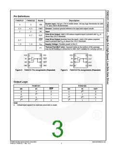
Figure 5. FAN3121 Pin Assignments (Repeated)
Figure 6. FAN3122 Pin Assignments (Repeated)
Output Logic
FAN3121
FAN3122
EN
0
IN
OUT
EN
0
IN
0(8)
1
OUT
0
0
0
1
0
0
0
0
1
0
1(8)
0
1(8)
0
1(8)
1(8)
1(8)
1(8)
0(8)
1
Note:
8. Default input signal if no external connection is made.
© 2008 Fairchild Semiconductor Corporation
FAN3121 / FAN3122 • Rev. 1.0.2
www.fairchildsemi.com
3

 FAIRCHILD [ FAIRCHILD SEMICONDUCTOR ]