XRT86L30
REV. 1.0.1
SINGLE T1/E1/J1 FRAMER/LIU COMBO
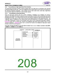
Multiplexed High-Speed Mode
10.2.2
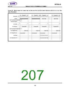
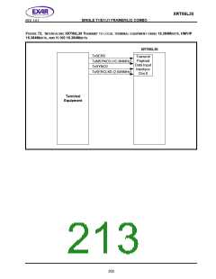
When the Back-plane interface data rate is 16.384Mbit/s, HMVIP 16.384Mbit/s, and H.100 16.384Mbit/s, the
interface signals are all configured as inputs, except the receive serial data on RxSER and the multi frame sync
pulse provided by the framer. The Transmit Serial Clock for each channel is always an input clock with
frequency of 2.048 MHz for all data rates so that it may be used as the timing reference for the transmit line
rate. The TxMSYNC signal is configured as the Transmit Input Clock with frequency of 16.384 MHz. It serves
as the primary clock source for the High-speed Back-plane Interface. Payload and signaling data of Channel
0-3 are multiplexed onto the Transmit Serial Data pin of Channel 0. Payload and signaling data of Channel 4-7
are multiplexed onto the Transmit Serial Data pin of Channel 4. The Transmit Single-frame Synchronization
signal of Channel 0 pulses HIGH at the beginning of the multiplexed frame with data from Channel 0-3
multiplexed together. The Transmit Single-frame Synchronization signal of Channel 4 pulses HIGH at the
beginning of the multiplexed frame with data from Channel 4-7 multiplexed together. It is the responsibility of
the Terminal Equipment to align the multiplexed transmit serial data with the Transmit Single-frame
Synchronization pulse. Additionally, each channel requires the local Terminal Equipment to provide a free-
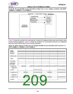
running 2.048 MHz clock into the Transmit Serial Clock input. The local Terminal Equipment maps four
2.048Mbit/s E1 data streams into one 16.384Mbit/s serial data stream as described below:
1. Payload data of four channels are repeated and grouped together in a bit-interleaved way. The first pay-
load bit of Timeslot 0 of Channel 0 is sent first, followed by the first payload bit of Timeslot 0 of Channel 1
and 2. The first payload bit of Timeslot 0 of Channel 3 is sent last.
After the first bit of Timeslot 0 of all four channels are sent, it comes the second bit of Timeslot 0 of
Channel 0 and so on. The table below demonstrates how payload bits of four channels are mapped into
the 16.384Mbit/s data stream.
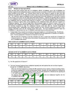
FIRST OCTET OF 16.384MBIT/S DATA STREAM
B
IT
0
B
IT
1
B
IT
2
B
IT
3
B
IT
4
4
B
IT
5
5
B
IT
6
6
B
IT
7
7
10
10
11
11
12
12
13
13
SECOND OCTET OF 16.384MBIT/S DATA STREAM
B
IT
0
B
IT
1
B
IT
2
B
IT
3
B
IT
B
IT
B
IT
B
IT
20
20
21
21
22
22
23
23
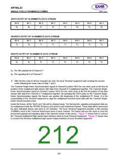
XY: The Xth payload bit of Channel Y
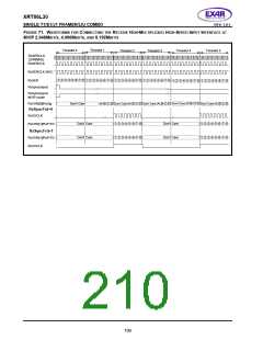
2. The local Terminal Equipment also multiplexed signaling bits with payload bits and sent them together
through the 16.384Mbit/s data stream.
When the Terminal Equipment is sending the fifth payload bit of one channel, instead of sending it twice,
it inserts the signaling bit A of that corresponding channel. Similarly, the sixth payload bit is followed by
the signaling bit B of that corresponding channel; the seventh payload bit is followed by the signaling bit
C; the eighth payload bit is followed by the signaling bit D.
The following table illustrates how payload bits and signaling bits are multiplexed together into the
16.384Mbit/s data stream.
FIFTH OCTET OF 16.384MBIT/S DATA STREAM
B
IT
0
B
IT
1
B
IT
2
B
IT
3
B
IT
4
B
IT
5
B
IT
6
BIT 7
50
A0
51
A1
52
A2
53
A3
200

 EXAR [ EXAR CORPORATION ]