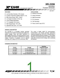
XR-2206
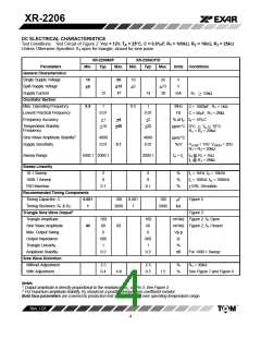
DC ELECTRICAL CHARACTERISTICS
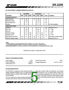
Test Conditions: Test Circuit of Figure 2 Vcc = 12V, T = 25°C, C = 0.01mF, R = 100kW, R = 10kW, R = 25kW
A
1
2
3
Unless Otherwise Specified. S open for triangle, closed for sine wave.
1
XR-2206M/P
Typ.
XR-2206CP/D
Parameters
General Characteristics
Single Supply Voltage
Split-Supply Voltage
Supply Current
Min.
Max.
Min.
Typ.
Max.
Units Conditions
10
+5
26
+13
17
10
+5
26
+13
20
V
V
12
14
mA
R1 ꢀ 10kW
Oscillator Section
Max. Operating Frequency
Lowest Practical Frequency
Frequency Accuracy
0.5
1
0.5
1
MHz
Hz
C = 1000pF, R1 = 1kW
C = 50mF, R1 = 2MW
0.01
+1
0.01
+2
+4
% of fo fo = 1/R1C
Temperature Stability
Frequency
+10
+50
+20
ppm/°C 0°C ꢁ TA ꢁ 70°C
R1 = R2 = 20kW
Sine Wave Amplitude Stability2
Supply Sensitivity
4800
0.01
4800
0.01
ppm/°C
0.1
%/V
VLOW = 10V, VHIGH = 20V,
R1 = R2 = 20kW
Sweep Range
1000:1 2000:1
2000:1
fH = fL fH @ R1 = 1kW
fL @ R1 = 2MW
Sweep Linearity
10:1 Sweep
2
8
2
8
%
%
%
fL = 1kHz, fH = 10kHz
1000:1 Sweep
FM Distortion
fL = 100Hz, fH = 100kHz
+10% Deviation
0.1
0.1
Recommended Timing Components
Timing Capacitor: C
Timing Resistors: R1 & R2
Triangle Sine Wave Output1
Triangle Amplitude
0.001
100
0.001
1
100
mF
Figure 5
1
2000
2000
kW
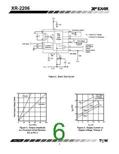
Figure 3
160
60
6
160
60
6
mV/kW Figure 2, S1 Open
Sine Wave Amplitude
Max. Output Swing
Output Impedance
40
80
mV/kW Figure 2, S1 Closed
Vp-p
W
600
1
600
1
Triangle Linearity
%
Amplitude Stability
0.5
0.5
dB
For 1000:1 Sweep
Sine Wave Distortion
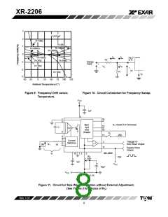
Without Adjustment
With Adjustment
2.5
0.4
2.5
0.5
%
%
R1 = 30kW
1.0
1.5
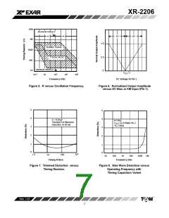
See Figure 7 and Figure 8
Notes
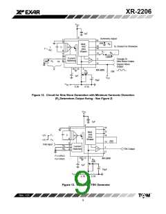
1 Output amplitude is directly proportional to the resistance, R3, on Pin 3. See Figure 3.
2 For maximum amplitude stability, R3 should be a positive temperature coefficient resistor.
Bold face parameters are covered by production test and guaranteed over operating temperature range.
Rev. 1.03
4

 EXAR [ EXAR CORPORATION ]