DESCRIPTION
the SP3080E - SP3088E are characterized for
protection to the following limits:
±15kV using the Human Body Model
±8kV using the Contact Discharge
method specified in IEC 1000-4-2
±15kV Air-gap
LOW POWER SHUTDOWN MODE
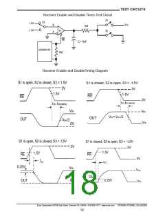
Low-power shutdown mode is initiated by bring-
ing both RE high and DE low simultaneously.
While in shutdown devices typically draw only
50nA of supply current. DE and RE may be tied
together and driven by a single control signal.
Devices are guaranteed not to enter shutdown
if RE is high and DE is low for less than 50ns. If
the inputs are in this state for at least 600ns, the
parts are shutdown.
ESD TEST CONDITIONS
ESD performance depends on a variety of
conditions. Contact Exar for a reliability report
that documents test setup, methodology and
results.
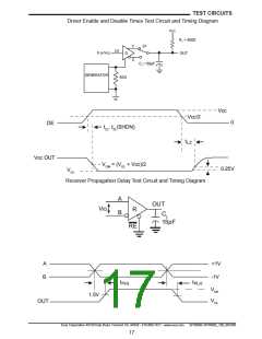
Enable times tZH and tZL apply when the part is
not in low-power shutdown state. Enable times
tZH(SHDN) and tZL(SHDN) apply when the parts
are shut down. The drivers and receivers take
longer to become enabled from low power shut-
down mode tZL(SHDN) and tZL(SHDN) than from
driver/receiver-disable mode (tZH, tZL).
IEC 1000-4-2
The IEC 1000-4-2 standard covers ESD testing
and performance of finished equipment. How-
ever, it does not specifically refer to integrated
circuits. The SP3080E family helps you design
equipment to meet IEC 1000-4-2, without sac-
rificing board space and cost for external ESD-
protection components.
DRIVER OUTPUT PROTECTION
Two mechanisms prevent excessive output cur-
rent and power dissipation caused by faults or
by bus contention. First, a driver-current limit
on the output stage provides immediate protec-
tion against short circuits over the whole com-
mon-mode voltage range. Second, a thermal-
shutdown circuit forces the driver outputs into
a high-impedance state if junction temperature
becomes excessive.
The major difference between tests done us-
ing the Human Body Model and IEC 1000-4-2
is a higher peak current in IEC 1000-4-2 series
resistance is lower in the IEC 1000-4-2 model.
Hence, the ESD withstand voltage measured to
IEC 1000-4-2 is generally lower than that mea-
sured using the human body model.
The air-gap test involves approaching the de-
vice with a charged probe. The contact dis-
charge method connects the probe to the de-
vice before the probe is energized.
LINE LENGTH, EMI, AND REFLECTIONS
SP3080E - SP3085E feature controlled slew-
rate drivers that minimize EMI and reduce reflec-
tions caused by improperly terminated cables.
MACHINE MODEL
The machine model for ESD tests all pins using
a 200pF storage capacitor and zero discharge
resistance. The objective is to emulate the
stress caused when I/O pins are contacted by
handling equipment during test and assembly.
SP3080E - SP3083E driver rise and fall times
are limited to no faster than 667ns, allowing er-
ror-free data transmission up to 115kbps. The
SP3083, SP3084 and SP3085 offer somewhat
higher driver output slew-rate limits, allowing
transmit speeds up to 500kbps.
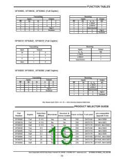
256 TRANSCEIVERS ON THE BUS
The standard RS-485 receiver input impedance
is 12kΩ (1 unit load). A standard driver can
drive up to 32 unit loads. The SP3080E fam-
ily of transceivers has only a 1/8th unit load re-
ceiver input impedance (96kΩ), thereby allow-
ing eight times as many, up to 256, transceivers
to be connected in parallel on a communication
line. Any combination of these devices and oth-
er RS-485 transceivers up to a total of 32 unit
loads may be connected to the line.
The RS-485/RS-422 standard covers line
lengths up to 4,000ft. Maximum achievable
line length is a function of signal attenuation
and noise. Use of slew-controlled drivers such
as the SP3080E-SP3086E may help to reduce
crosstalk interference and permit communica-
tion over longer transmission lines.
Exar Corporation 48720 Kato Road, Fremont CA, 94538 • 510-668-7017 • www.exar.com
SP3080E-SP3088E_100_062309
21

 EXAR [ EXAR CORPORATION ]