EUP8084
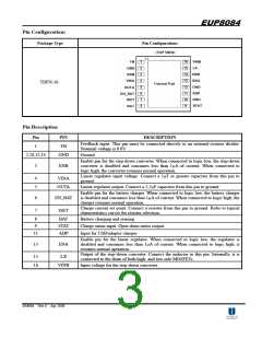
Pin Configurations
Package Type
Pin Configurations
TDFN-16
Pin Description
Pin
1
PIN
FB
DESCRIPTION
Feedback input. This pin must be connected directly to an external resistor divider.
Nominal voltage is 0.6V.
2,10,12,14
GND
Ground.
Enable pin for the step-down converter. When connected to logic low, the step-down
converter is disabled and consumes less than 1µA of current. When connected to
logic high, the converter resumes normal operation.
3
ENB
Linear regulator input voltage. Connect a 1µF or greater capacitor from this pin to
4
5
VINA
OUTA
ground.
Linear regulator output. Connect a 2.2µF capacitor from this pin to ground.
Enable pin for the battery charger. When connected to logic low, the battery charger
is disabled and consumes less than 1µA of current. When connected to logic high, the
charger resumes normal operation.
6
EN_BAT
Charge current set point. Connect a resistor from this pin to ground. Refer to typical
7
ISET
characteristics curves for resistor selection.
8
9
BAT
STAT
ADP
Battery charging and sensing.
Charge status input. Open drain status output.
Input for USB/adapter charger.
11
Enable pin for the linear regulator. When connected to logic low, the regulator is
disabled and consumes less than 1µA of current. When connected to logic high, it
resumes normal operation.
13
ENA
Output of the step-down converter. Connect the inductor to this pin. Internally, it is
15
16
LX
connected to the drain of both high- and low-side MOSFETs.
Input voltage for the step-down converter.
VINB
DS8084 Ver1.0 Apr. 2008
3

 EUTECH [ EUTECH MICROELECTRONICS INC ]