PR8275
High Voltage Start-Up PWM Controller
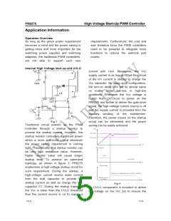
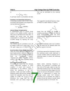
supplyꢀ voltageꢀ enoughꢀ toꢀ powerꢀ onꢀ theꢀ
PR8275ꢀ PWMꢀ controllerꢀ andꢀ inꢀ additionꢀ toꢀ
driveꢀtheꢀpowerꢀMOSFET.ꢀAsꢀshownꢀinꢀFig.ꢀ
4,ꢀ aꢀ hysistersisꢀ isꢀ providedꢀ toꢀ preventꢀ theꢀ
shutdownꢀfromꢀtheꢀvoltageꢀdipꢀduringꢀstartup.ꢀ
Theꢀturnꢁonꢀandꢀturnꢁoffꢀthresholdꢀlevelꢀareꢀ
setꢀatꢀ16Vꢀandꢀ10.0V,ꢀrespectively.ꢀ
Current Sensing, Leading-edge Blanking
and the Negative Spike on CS Pin
Theꢀ typicalꢀ currentꢀ modeꢀ PWMꢀ controllerꢀ
feedbacksꢀ bothꢀ currentꢀ signalꢀ andꢀ voltageꢀ
signalꢀtoꢀcloseꢀtheꢀcontrolꢀloopꢀandꢀachieveꢀ
regulation.ꢀTheꢀPR8275ꢀdetectsꢀtheꢀprimaryꢀ
MOSFETꢀcurrentꢀfromꢀtheꢀCSꢀpin,ꢀwhichꢀisꢀ
notꢀ onlyꢀ forꢀtheꢀ peakꢀcurrentꢀmodeꢀ controlꢀ
butꢀalsoꢀforꢀtheꢀpulseꢁbyꢁpulseꢀcurrentꢀlimit.ꢀ
Theꢀ maximumꢀ voltageꢀ thresholdꢀ ofꢀ theꢀ
currentꢀsensingꢀpinꢀisꢀsetꢀasꢀ0.85V.ꢀThusꢀtheꢀ
MOSFETꢀpeakꢀcurrentꢀcanꢀbeꢀcalculatedꢀas:ꢀ
0.85 ꢀ
Rs
Ipeak (max.) =
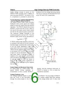
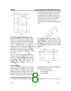
Aꢀ350nSꢀleadingꢁedgeꢀblankingꢀ(LEB)ꢀtimeꢀ
isꢀincludedꢀinꢀtheꢀinputꢀofꢀCSꢀpinꢀtoꢀpreventꢀ
theꢀfalseꢁtriggerꢀcausedꢀbyꢀtheꢀcurrentꢀspike.ꢀ
Inꢀ theꢀ lowꢀ powerꢀ application,ꢀ ifꢀ theꢀ totalꢀ
pulseꢀwidthꢀofꢀtheꢀturnꢁonꢀspikesꢀisꢀlessꢀthanꢀ
350nSꢀandꢀtheꢀnegativeꢀspikeꢀonꢀtheꢀCSꢀpinꢀ
isꢀnotꢀexceedꢀꢁ0.3V,ꢀtheꢀRꢁCꢀfilterꢀ(asꢀshownꢀ
inꢀfigureꢀ5)ꢀcanꢀbeꢀeliminated.ꢀHowever,ꢀtheꢀ
totalꢀ pulseꢀ widthꢀ ofꢀ theꢀ turnꢁonꢀ spikeꢀ isꢀ
relatedꢀ toꢀ theꢀ outputꢀ power,ꢀ circuitꢀ designꢀ
andꢀPCBꢀlayout.ꢀItꢀisꢀstronglyꢀrecommendedꢀ
toꢀ addꢀ theꢀ smallꢀ RꢁCꢀ filterꢀ (asꢀ shownꢀ inꢀ
figureꢀ 6)ꢀ forꢀ higherꢀ powerꢀ applicationꢀ toꢀ
avoidꢀtheꢀCSꢀpinꢀdamagedꢀbyꢀtheꢀnegativeꢀ
turnꢁonꢀspike.ꢀ
Fig.5
Fig.6
ꢀ
Output Stage and Maximum Duty-Cycle
Anꢀ outputꢀ stageꢀ ofꢀ aꢀ CMOSꢀ buffer,ꢀ withꢀ
directly.ꢀ Andꢀ theꢀ maximumꢀ dutyꢁcycleꢀ ofꢀ
PR8275ꢀ isꢀ limitedꢀ toꢀ 75%ꢀ toꢀ avoidꢀ theꢀ
transformerꢀsaturation.ꢀ
typicalꢀ 500mAꢀ drivingꢀ capability,ꢀ isꢀ
incorporatedꢀ toꢀ driveꢀ aꢀ powerꢀ MOSFETꢀ
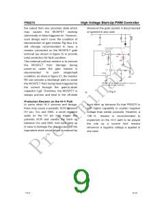
Voltage Feedback Loop
Theꢀ voltageꢀ feedbackꢀ signalꢀ isꢀ providedꢀ
pinꢀofꢀPR8275.ꢀTheꢀinputꢀstageꢀofꢀPR8275ꢀ
withꢀ 2ꢀ diodesꢀ voltageꢀ offsetꢀ thenꢀ feedingꢀ
intoꢀtheꢀvoltageꢀdividerꢀwithꢀ1/3ꢀratio,ꢀthatꢀ
fromꢀ theꢀ TL431ꢀ inꢀ theꢀ secondaryꢀ sideꢀ
throughꢀ theꢀ photoꢁcouplerꢀ toꢀ theꢀ COMPꢀ
V1.0
6/10

 ETC [ ETC ]