Ericsson Internal
E
EJUNBLI
PRODUCT SPECIFICATION
4 (5)
Prepared (also subject responsible if other)
No.
2/1301-BMR 637 02/E4 Uen
16
Technical Specification
Approved
Checked
Date
Rev
EN/LZT 146 3R0e6feRre4nAceJuly 2008
PKM 4000D PINB Series
SEC/D (ALICE SU)
ESKEVIN
2008-7-16
A
© Ericsson Power Modules AB
DC/DC converters, Input 36-75 V, Output 40 A/132 W
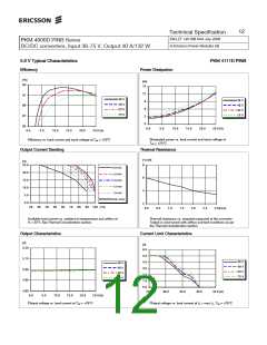
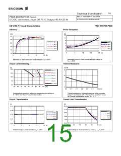
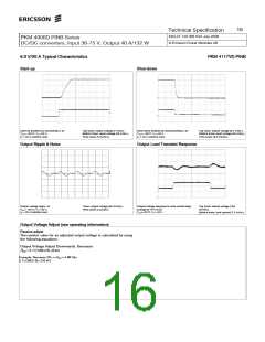
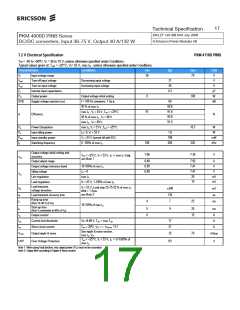
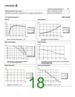
6.0 V/20 A Typical Characteristics
PKM 4117VD PINB
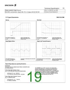
Start-up
Shut-down
Start-up enabled by connecting VI at:
Top trace: output voltage (2 V/div.).
Bottom trace: input voltage (20 V/div.).
Time scale: (5 ms/div.).
Shut-down enabled by disconnecting VI at:
Tref = +25°C, VI = 53 V,
IO = 20 A resistive load.
Top trace: output voltage (0.5 V/div.).
Bottom trace: input voltage (20 V/div.).
Time scale: (0.5 ms/div.).
Tref = +25°C, VI = 53 V,
IO = 20 A resistive load.
Output Ripple & Noise
Output Load Transient Response
Output voltage ripple at:
Tref = +25°C, VI = 53 V,
Trace: output voltage (50 mV/div.).
Time scale: (2 µs/div.).
Output voltage response to load current step-
change (5-15-5 A) at:
Tref =+25°C, VI = 53 V.
Top trace: output voltage (100
mV/div.).
Bottom trace: load current (7.5 A/div.).
I
O = 20 A resistive load.
Output Voltage Adjust (see operating information)
Passive adjust
The resistor value for an adjusted output voltage is calculated by using
the following equations:
Output Voltage Adjust Downwards, Decrease:
Radj= 5.11(100/∆%-2) kΩ
Example: Decrease 2% =>Vout = 5.88 Vdc
5.11(100/2-2)= 245 kΩ

 ERICSSON [ ERICSSON ]