Ericsson Internal
EBAOCMA
PRODUCT SPECIFICATION
4 (5)
Prepared (also subject responsible if other)
No.
3/1301-BMR 637 02
20
Technical Specification
Approved
Checked
Date
Rev
Reference
EN/LZT 146 306 R2C Jan 2007
PKM 4000D PINB series
DC/DC converters, Input 36-75 V, Output 40 A/132 W
MPM/BK [Andréas Svensson]
MICOSPE
2006-9-13
A
© Ericsson Power Modules AB
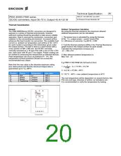
Thermal Consideration
General
Ambient Temperature Calculation
By using the thermal resistance the maximum allowed
ambient temperature can be calculated.
The PKM 4000DSeries DC/DC converters are designed to
operate in a variety of thermal environments, however
sufficient cooling should be provided to help ensure reliable
operation. Heat is removed by conduction, convection and
radiation to the surrounding environment. Increased airflow
enhances the heat transfer via convection. The available load
current vs. ambient air temperature and airflow at Vin =53 V
for each model is according to the information given under
the output section. The test is done in a wind tunnel with a
cross section of 305 x 305 mm, the DC/DC converter
vertically mounted on a 16 layer Pcb with a size of 254 x 254
mm, each layer with 35 µm (1 oz) copper. Proper cooling can
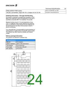
be verified by measuring the temperature of selected devices.
Peak temperature can occur at positions P1 - P4. The
temperature at these positions should not exceed the
recommended max values.
1. The power loss is calculated by using the formula
((1/η) - 1) × output power = power losses (Pd).
η = efficiency of converter. E.g 90 % = 0.90
2. Find the thermal resistance (Rth) in the Thermal Resistance
graph found in the Output section for each model.
Calculate the temperature increase (∆T).
∆T = Rth x Pd
3. Max allowed ambient temperature is:
Max Tref - ∆T.
E.g PKM 4110D PINB 53v full load at 2m/s:
1
Note that the max value is the absolute maximum rating
(non destruction) and that the electrical Output data is
guaranteed up to Tref +90°C.
1. ((
) - 1) × 115 W = 14.2 W
0.89
2. 14.2 W × 4°C/W = 56°C
Position
Device
Pcb
Mosfet
Mosfet
Transformer
Designation
Tref
Tsurface
Tsurface
Tsurface
max value
3. 110 °C - 56°C = max ambient temperature is 54°C
P1
P2
P3
P4
110º C
120º C
120º C
130º C
The real temperature will be dependent on several factors, like
Pcb size and type, direction of airflow, air turbulence etc.
It is recommended to verify the temperature by testing.

 ERICSSON [ ERICSSON ]