PBL 386 30/2
Notes
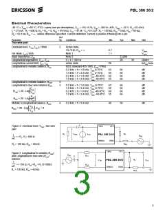
1. The overload level can be adjusted with the ROV resistor
for higher levels e.g. min 3.1 VPeak and is specified at the
two-wire port with the signal source at the four-wire
receive port.
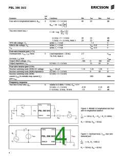
4. The overload level level can be adjusted with the ROV
resistor for higher levels e.g. min 3.1 VPeak and is specified
at the four-wire transmit port, VTX, with the signal source
at the two-wire port. Note that the gain from the two-wire
port to the four-wire transmit port is G2-4S = 1 (or 0.5 see
pin PTG)
2. The two-wire impedance is programmable by selection of
external component values according to:
ZTRX = ZT/|G2-4S α RSN| where:
5. Pin PTG = Open sets transmit gain to nom. 0.0dB
Pin PTG = AGND sets transmit gain to nom. -6.02 dB
Secondary protection resistors RF impact the insertion loss
as explained in the text, section Transmission. The
specified insertion loss is for RF = RP = 0.
6. The specified insertion loss tolerance does not include
errors caused by external components.
7. The level is specified at the two-wire port.
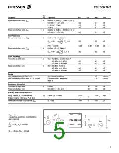
8. The two-wire idle noise is specified with the port
terminated in 600 Ω (RL) and with the four-wire receive
port grounded (ERX = 0; see figure 6).
ZTRX = impedance between the TIPX and RINGX
terminals
ZT = programming network between the VTX and RSN
terminals
G2-4S = transmit gain, nominally = 1 (or 0.5 see pin PTG)
α
RSN = receive current gain, nominally = 200 (current
defined as positive flowing into the receivesumm-
ing node, RSN, and when flowing from ring to tip).
3. Higher return loss values can be achieved by adding a
reactive component to RT, the two-wire terminating
impedance programming resistance, e.g. by dividing RT
into two equal halves and connecting a capacitor from the
common point to ground.
The four-wire idle noise at VTX is specified with the two-
wire port terminated in 600 Ω (RL). The noise specification
is referenced to a 600 Ω programmed two-wire impedance
level at VTX. The four-wire receive port is grounded
(ERX = 0).
7

 ERICSSON [ ERICSSON ]