EL2074C
400MHz GBWP Gain-of-2 Stable Operational Amplifier
Applications Information
the gain resistor. The problem stems from the feedback
Product Description
and gain resistance in conjunction with the approxi-
mately 3pF of board-related parasitic capacitance from
the inverting input to ground. Assuming a gain-of-2 con-
figuration with RF = RG = 250W, a feedback pole occurs
at 424MHz, which is equivalent to a zero in the forward
path at the same frequency. This zero reduces stability
by reducing the effective phase-margin from about 50°
to about 30°.
The EL2074C is a wideband monolithic operational
amplifier built on a high-speed complementary bipolar
process. The EL2074C uses a classical voltage-feedback
topology which allows it to be used in a variety of appli-
cations requiring a noise gain ³ 2 where current-feedback
amplifiers are not appropriate because of restrictions
placed upon the feedback element used with the ampli-
fier. The conventional topology of the EL2074C allows,
for example, a capacitor to be placed in the feedback
path, making it an excellent choice for applications such
as active filters, sample-and-holds, or integrators. Simi-
larly, because of the ability to use diodes in the feedback
network, the EL2074C is an excellent choice for appli-
cations such as log amplifiers.
A common solution to this problem is to add an addi-
tional capacitor from the inverting input to the output.
This capacitor, in conjunction with the parasitic capaci-
tance, maintains a constant voltage-divider between the
output and the inverting input. This technique is used for
AC testing of the EL2074. A 3pF capacitor is placed in
parallel with the feedback resistor for all AC tests. When
this capacitor is used, it is also possible to increase the
resistance values of the feedback and gain resistors with-
out loss of stability, resulting in less loading of the
EL2074C from the feedback network.
The EL2074C also has excellent DC specifications:
200µV, VOS, 2µA IB, 0.1µA IOS, and 90dB of CMRR.
These specifications allow the EL2074C to be used in
DC-sensitive applications such as difference amplifiers.
Furthermore, the current noise of the EL2074C is only
3.2pA/ÖHz, making it an excellent choice for high-sen-
sitivity transimpedance amplifier configurations.
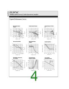
Video Performance
An industry-standard method of measuring the video
distortion of a component such as the EL2074C is to
measure the amount of differential gain (dG) and differ-
ential phase (dP) that it introduces. To make these
measurements, a 0.286VPP (40 IRE) signal is applied to
the device with 0V DC offset (0 IRE) at either 3.58MHz
for NTSC, 4.43MHz for PAL, or 30MHz for HDTV. A
second measurement is then made at 0.714V DC offset
(100 IRE). Differential gain is a measure of the change
in amplitude of the sine wave, and is measured in per-
cent. Differential phase is a measure of the change in
phase, and is measured in degrees.
Gain-Bandwidth Product
The EL2074C has a gain-bandwidth product of
400MHz. For gains greater than 8, its closed-loop -3dB
bandwidth is approximately equal to the gain-bandwidth
product divided by the noise gain of the circuit. For
gains less than 8, higher-order poles in the amplifier's
transfer function contribute to even higher closed loop
bandwidths. For example, the EL2074C has a -3dB
bandwidth of 400MHz at a gain of +2, dropping to
200MHz at a gain of +4. It is important to note that the
EL2074C has been designed so that this “extra” band-
width in low-gain applications does not come at the
expense of stability. As seen in the typical performance
curves, the EL2074C in a gain of +2 only exhibits 1dB
of peaking with a 100W load.
For signal transmission and distribution, a back-termi-
nated cable (75W in series at the drive end, and 75W to
ground at the receiving end) is preferred since the
impedance match at both ends will absorb any reflec-
tions. However, when double termination is used, the
received signal is halved; therefore a gain of 2 configu-
ration is typically used to compensate for the
attenuation.
Parasitic Capacitances and Stability
When used in positive-gain configurations, the
EL2074C can be quite sensitive to parasitic capacitances
at the inverting input, especially with values ³ 250W for
8

 ELANTEC [ ELANTEC SEMICONDUCTOR ]