AP1117/AP1117I
Application Information
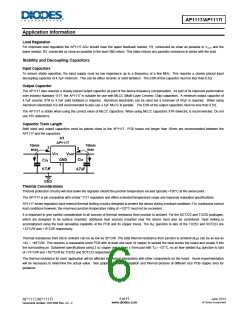
Load Regulation
For improved load regulation the AP1117-ADJ should have the upper feedback resistor, R1, connected as close as possible to VOUT and the
lower resistor, R2, connected as close as possible to the load GND return. This helps reduce any parasitic resistance in series with the load.
Stability and Decoupling Capacitors
Input Capacitors
To ensure stable operation, the input supply must be low impedance up to a frequency of a few MHz. This requires a closely placed input
decoupling capacitor of 4.7µF minimum. This can be either ceramic or solid tantalum. The ESR of this capacitor must be less than 0.5Ω.
Output Capacitor
The AP1117 also requires a closely placed output capacitor as part of the device frequency compensation. As part of its improved performance
over industry standard 1117, the AP1117 is suitable for use with MLCC (Multi-Layer Ceramic Chip) capacitors. A minimum output capacitor of
4.7µF ceramic X7R or 4.7µF solid tantalum is required. Aluminum electrolytic can be used but a minimum of 47µF is required. When using
Aluminum electrolytic it is still recommended to also use a 1µF MLCC in parallel. The ESR of the output capacitors must be less than 0.5ꢀ.
The AP1117 is stable when using the correct value of MLCC capacitors. When using MLCC capacitors X7R dielectric is recommended. Do not
use Y5V dielectrics.
Capacitor Track Length
Both input and output capacitors must be placed close to the AP1117. PCB traces not longer than 10mm are recommended between the
AP1117 and the capacitors.
Thermal Considerations
Thermal protection circuitry will shut down the regulator should the junction temperature exceed typically +150°C at the sense point.
The AP1117 is pin compatible with similar ‘1117 regulators and offers extended temperature range and improved regulation specifications.
AP1117 series regulators have internal thermal limiting circuitry designed to protect the device during overload conditions. For continuous normal
load conditions however, the maximum junction temperature rating of +125°C must not be exceeded.
It is important to give careful consideration to all sources of thermal resistance from junction to ambient. For the SOT223 and TO252 packages,
which are designed to be surface mounted, additional heat sources mounted near the device must also be considered. Heat sinking is
accomplished using the heat spreading capability of the PCB and its copper traces. The θJC (junction to tab) of the TO252 and SOT223 are
+12°C/W and +15°C/W respectively.
Thermal resistances from tab to ambient can be as low as 30°C/W. The total thermal resistance from junction to ambient (θJA) can be as low as
+42 ~ +46°C/W. This requires a reasonable sized PCB with at least one layer of copper to spread the heat across the board and couple it into
the surrounding air. Datasheet specifications using 2 oz copper and a 5mm x 5mm pad with TA = +27°C, no air flow yielded θJA (junction to tab)
of +73°C/W and +107°C/W for TO252 and SOT223 respectively.
The thermal resistance for each application will be affected by thermal interactions with other components on the board. Some experimentation
will be necessary to determine the actual value. See graphs of power dissipation and thermal pictures of different size PCB copper area for
guidance.
6 of 13
www.diodes.com
June 2013
© Diodes Incorporated
AP1117/AP1117I
Document number: DS31009 Rev. 23 - 2

 DIODES [ DIODES INCORPORATED ]