DS3251/DS3252/DS3253/DS3254
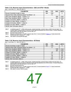
Table 17-D. Receiver Input Characteristics—DS3 and STS-1 Modes
(VDD = 3.3V M5%, TA = -40°C to +85°C.)
PARAMETER
MIN
TYP
MAX
UNITS
Receive Sensitivity (Length of Cable)
900
1200
10
ft
Signal-to-Noise Ratio, Interfering Signal Test (Notes 1, 2)
Input Pulse Amplitude, RMON = 0 (Notes 2, 3)
Input Pulse Amplitude, RMON = 1 (Note 2, 3)
Analog LOS Declare, RMON = 0 (Note 4)
Analog LOS Clear, RMON = 0 (Note 4)
Analog LOS Declare, RMON = 1 (Note 4)
Analog LOS Clear, RMON = 1 (Note 4)
Intrinsic Jitter Generation (Note 2)
1000
200
mVpk
mVpk
dB
-24
-21
-38
-35
dB
dB
dB
0.03
UIP-P
Note 1:
An interfering signal (215 - 1 PRBS, B3ZS encoded, compliant waveshape, nominal bit rate) is added to the input signal. The
combined signal is passed through 0 to 900 feet of coaxial cable and presented to the DS325x receiver. This spec indicates the
lowest signal-to-noise ratio that results in a bit error ratio ?10-9.
Note 2:
Note 3:
Not tested during production test.
Measured on the line side (i.e., the BNC connector side) of the 1:2 receive transformer (Figure 2-1). During measurement,
incoming data traffic is unframed 215 - 1 PRBS.
Note 4:
With respect to nominal 800mVpk signal.
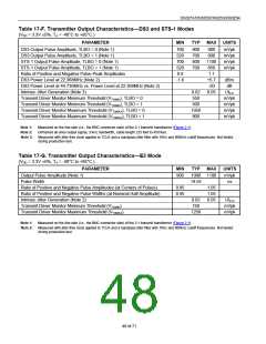
Table 17-E. Receiver Input Characteristics—E3 Mode
(VDD = 3.3V M5%, TA = -40°C to +85°C.)
PARAMETER
Receive Sensitivity (Length of Cable)
MIN
900
TYP
1200
12
MAX
UNITS
ft
Signal-to-Noise Ratio, Interfering Signal Test (Notes 1, 2)
Input Pulse Amplitude, RMON = 0 (Notes 2, 3)
Input Pulse Amplitude, RMON = 1 (Notes 2, 3)
Analog LOS Declare, RMON = 0 (Note 4)
Analog LOS Clear, RMON = 0 (Note 4)
Analog LOS Declare, RMON = 1 (Note 4)
Analog LOS Clear, RMON = 1 (Note 4)
Intrinsic Jitter Generation (Note 2)
1300
260
mVpk
mVpk
dB
-24
-21
-38
-35
dB
dB
dB
0.03
UIP-P
Note 1:
An interfering signal (223 - 1 PRBS, HDB3 encoded, compliant waveshape, nominal bit rate) is added to the input signal. The
combined signal is passed through 0 to 900 feet of coaxial cable and presented to the DS325x receiver. This spec indicates the
lowest signal-to-noise ratio that results in a bit error ratio ?10-9.
Not tested during production test.
Note 2:
Note 3:
Measured on the line side (i.e., the BNC connector side) of the 1:2 receive transformer (Figure 2-1). During measurement,
incoming data traffic is unframed 223 - 1 PRBS.
Note 4:
With respect to nominal 1000mVpk signal.
47 of 71

 DALLAS [ DALLAS SEMICONDUCTOR ]