ES51993
11,000 Counts ADC
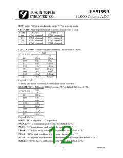
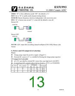
ZERO: “H” is Zero calibration mode “ON”, the default is “L”
ROT: Set to ”H” to enable multi channel rotating feature
B2/B1/B0: Buzzer frequency selection (independent with conversion rate)
BUZ: “H” is buzzer turn on and “L” is turn off, the default is turn off.
Buzzer ON
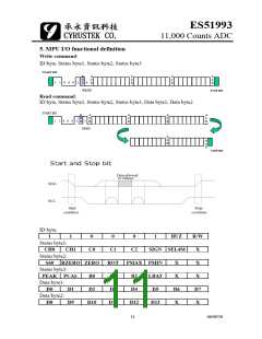
START BIT
A
C
1
1
0
0
0
0
0
0
1
1
1
0
K
STOP BIT
Buzzer OFF
START BIT
A
C
K
1
1
STOP BIT
D13-D0: ADC output data according channel multiplex [CH1/CH0]. Binary code
format.
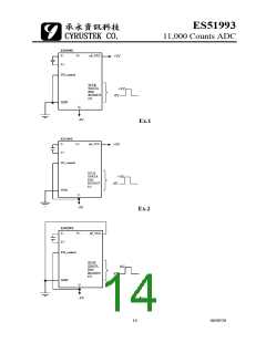
6. Power and I/O output level selection
Power
z Charge pump output for positive supply voltage(V+)
z External DC source to V+ is available by floating the charge pump capacitor
I/O output level selectable
z uP_VCC provided by external DC source (the same high level with MPU)
z A control pin (I/O_control) selects the low level to –3V(V-) or 0V(DGND)
I/O level
uP_VCC I/O_control
Example
H
L
3
3
0
H
L
L
+3V
+3V
0V
0V
Ex.1
Ex.2
Ex.3
-3V
-3V
13
06/09/20

 CYRUSTEK [ Cyrustek corporation ]