CY7C68013A/CY7C68014A
CY7C68015A/CY7C68016A
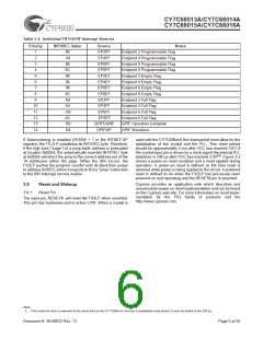
3.12.3 Set-up Data Buffer
3.12
Endpoint RAM
A separate 8-byte buffer at 0xE6B8-0xE6BF holds the Set-up
data from a CONTROL transfer.
3.12.1 Size
• 3× 64 bytes
(Endpoints 0 and 1)
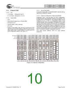
3.12.4 Endpoint Configurations (High-speed Mode)
• 8 × 512 bytes (Endpoints 2, 4, 6, 8)
Endpoints 0 and 1 are the same for every configuration.
Endpoint 0 is the only CONTROL endpoint, and endpoint 1 can
be either BULK or INTERRUPT. The endpoint buffers can be
configured in any 1 of the 12 configurations shown in the
vertical columns. When operating in full-speed BULK mode
only the first 64 bytes of each buffer are used. For example in
high-speed, the max packet size is 512 bytes but in full-speed
it is 64 bytes. Even though a buffer is configured to be a 512
byte buffer, in full-speed only the first 64 bytes are used. The
unused endpoint buffer space is not available for other opera-
tions. An example endpoint configuration would be:
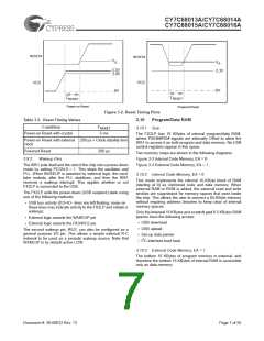
3.12.2 Organization
• EP0
• Bidirectional endpoint zero, 64-byte buffer
• EP1IN, EP1OUT
• 64-byte buffers, bulk or interrupt
• EP2,4,6,8
• Eight 512-byte buffers, bulk, interrupt, or isochronous. EP4
and EP8 can be double buffered, while EP2 and 6 can be
either double, triple, or quad buffered. For high-speed end-
point configuration options, see Figure 3-5.
EP2—1024 double buffered; EP6—512 quad buffered
(column 8).
64
64
64
64
64
64
64
64
64
64
64
64
64
64
64
64
64
64
64
64
64
64
64
64
64
64
64
64
64
64
64
64
64
64
64
64
EP0 IN&OUT
EP1 IN
EP1 OUT
EP2
512
EP2
EP2
EP2 EP2
EP2 EP2
EP2
512
EP2
EP2
EP2
512
EP2
512
512
512
512
512
512
512
1024
1024
1024
1024
512
512
512
512
512
1024
EP4
512
EP4 EP4
512
512
512
512
512
512
512
512
EP6
1024
1024
1024
1024
1024
1024
512
512
512
512
EP6
512
EP6
512
EP6
EP6 EP6
EP6
EP6
EP6 EP6
512
512
1024
1024
512
512
512
512
512
512
1024
1024
1024
512
512
512
512
EP8
512
EP8
512
EP8
512
EP8
512
EP8
512
1024
512
512
512
512
512
512
1024
1024
1024
512
512
512
512
512
10
12
9
11
4
5
8
1
2
7
3
6
Figure 3-5. Endpoint Configuration
Document #: 38-08032 Rev. *G
Page 10 of 55

 CYPRESS [ CYPRESS ]