Introduction
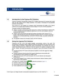
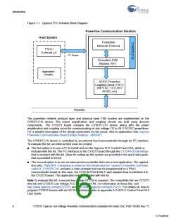
Figure 1-1. Cypress PLC Solution Block Diagram
Powerline Communication Solution
Host System
Powerline
Network Protocol
PSoC/
External µC
I2C Packet
Powerline FSK
Modem PHY
Application
Circuitry
AC/DC Powerline
Coupling Circuit (110 V-
240 V AC, 12 V-24 V
AC/DC, etc)
Powerline
The powerline network protocol layer and physical layer FSK modem are implemented on the
CY8CPLC10 device. The power amplification and coupling circuits are built using discrete
components. The CY3273 board contains the CY8CPLC10 device along with the power
amplification and coupling circuit for communicating on low voltage (12 to 24 V AC/DC) powerlines.
For a detailed description of the design parameters for the circuit, refer to application note Cypress
Powerline Communication Board Design Analysis - AN55427.
2
The CY8CPLC10 device is controlled by an external host microcontroller through an I C interface.
To evaluate this kit, an external host must be created.
■
The first option is to use a PC to install and run the Cypress PLC Control Panel GUI, which is
included with this kit. The PC interfaces to the CY3273 board through the CY3240-I2USB Bridge
that is included with this kit. Steps for setting up this system are provided in the quick start guide
that is provided in the kit.
■
The second option is to use an external microcontroller that runs a host application. The applica-
tion note, “AN52478 - Designing an external Host Application for Cypress's Powerline Communi-
cation IC CY8CPLC10, provides a code example that can be programmed on a PSoC
microcontroller board (in this case, the CY3210-PSoCEVAL1) and explains how to interface it to
the CY3273 board. This application note is provided with this kit.
Note To evaluate this kit, a second low voltage PLC kit is required. The compatible kits are CY3273
(this kit) and CY3275 Low Voltage PLC Development Kit. For information on these kits, visit
http://www.cypress.com/go/CY3273 and http://www.cypress.com/go/CY3275. For details on how to
program CY3275 boards with an I2C-PLC interface, refer to appendix A.2 of PLC Control Panel GUI
User Guide.
6
CY3273 Cypress Low Voltage Powerline Communication Evaluation Kit Guide, Doc. # 001-55382 Rev. *C
[+] Feedback

 CYPRESS [ CYPRESS ]